


Smart Tower UPS 10-30KVA User Manual
Chapter 4 Installation of Parallel Operation System
19
Chapter 4 Installation of Parallel Operation System
The parallel operation system installation is of same procedures of the installation the single system
requirement and this chapter.
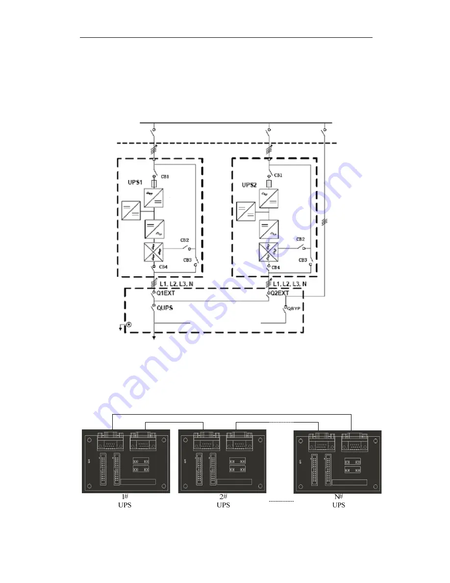
The single devices should be located parallel and be connected as shown in fig. 4-1, the difference is
that the lengths of the output cables of the single devices is not more than 10m. It is recommended to use
an external bypass cabinet to facilitate maintenance and system testing.
Fig. 4-1 Typical 1+N parallel operation system
Note: when the load exceeds the capacity of a single device, the maintenance bypass switch
CB3 must be removed.
The parallel operation need double insulation shielded cable up to 30m long, the control cables for
the parallel operation must be connected all the single devices to form a closed loop, as shown in fig.4-2.
Fig.4-2 parallel cables
Other power supplies
Rectifier
Charger
Inverter
Inverter
Output power supply
Load connected
Mains power input,
L1, L2, L3, N terminals
Mains power input,
L1, L2, L3, N terminals
Rectifier
Charger