CyberOptics Corporation
109
Conveyor Components
Replacing the Pulley Drive
Use this procedure to replace the pulley drive from the railsets. This procedure can be
performed with access to the left/right of the machine in production line. This section shows
the procedure performed when the machine is not in production line.
Parts
Pulley drive
Required Tools
–
No. 2.5 Allen Key
–
No. 3 Allen Key
➢
To replace the conveyor pulley drive
1. Make sure the sensor is at the HOME position without blocking any portion of the rail.
2. Make sure the clamp blade at the rails are in the “OPEN” position.
3. Turn off all electrical power to the system. For more information, refer to the section
4. Open the front cover from the machine.
5. Loosen the Idler Pulley No. 2 by using the No. 3 Allen Key at the setscrew.
6. Slide the Idler pulley towards the motor direction in order to relieve the belt tension.
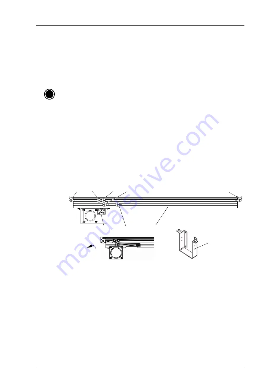
7. Remove the belt from the pulley drive first, followed by the sequence with pulley No. 3 & 5.
8. Turn the pulley-drive setscrew facing to the bracket motor M4 screw hole and use the No. 2.5
Allen Key to loosen the two setscrews.
9. Remove the pulley drive from the bracket motor.
10. Replace a new pulley drive, fixed it to the motor shaft and tighten it with two setscrews
using the No. 2.5 Allen Key.
11. Route the new belt following the sequence starting at pulley No. 1, followed by pulley No. 2,
pulley No. 3, pulley No. 4, drive pulley, pulley No. 5 and lastly pulley No. 6 as shown in
Figure 57.
12. Push the Idler pulley No. 2 at 6kgf by using the Push-Pull gauge.
13. Tighten the setscrew to pulley No. 2 after applying adequate amount of threadlocking
sealant.
i
Note:
For Parts Replacement, contact CyberOptics for part numbers.
Holes for Allen
Key (both sides)
on motor bracket
Direction of the
setscrew
Pulley 1
Pulley 2
Pulley 3
Pulley 4
Pulley 5
Pulley 6
Railset
Drive pulley
Summary of Contents for SE500ULTRA
Page 1: ...SE500ULTRA Hardware Manual ...
Page 6: ...Contents vi SE500ULTRA Hardware Manual ...
Page 10: ...x SE500ULTRA Hardware Manual This page is intentionally left blank ...
Page 28: ...Chapter 1 System Overview 18 SE500ULTRA Hardware Manual Dimensions Figure 8 Front View ...
Page 30: ...Chapter 1 System Overview 20 SE500ULTRA Hardware Manual ...
Page 184: ...Chapter 5 System Drawings 174 CyberOptics Corporation ...


