16
the battery.
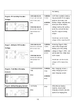
Page 6 - PV to Utility Transfer
Voltage
CPD1200EO12LCD:
11.0/11.3/11.5/11.8/12.
0/12.3/12.5/12.8V/
ESC
CPD2200EO24LCD:
22.0/22.5/23.0/23.5/24.
0/24.5/25.0/25.5V/
ESC
1200VA:
11.5V
2200VA:
23.0V
In PV first condition, battery
may work with PV to supply
power to the loads, and
battery voltage will gradually
decrease. When battery
voltage reaches the setting
point, the unit will transfer
from PV output to Utility
output.
Note: Make sure the transfer
voltage in P06 is lower than P07.
Page 7 - Utility to PV Transfer
Voltage
CPD1200EO12LCD:
FUL/12.0/12.3/12.5/12.
8/13.0/13.3/13.5V/
ESC
CPD2200EO24LCD:
FUL/24.0/24.5/25.0/25.
5/26.0/26.5/27.0V/
ESC
1200VA:
13.5V
2200VA:
27.0V
Following Page 6 (P06),
when utility charges the
battery up to the setting
voltage in Page 7 (P07), unit
will transfer from Utility back
to PV mode.
Note: Make sure the transfer
voltage in P07 is higher than
P06.
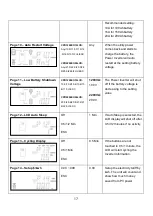
Page 8 - Total Max. Charging
Current
10/20/30/40/50/60/
70A
ESC
1200VA:
70A
2200VA:
65A
Max. charging current =
utility charging c
solar charging current
Page 9 - Utility Charging Current
10/15/20A
ESC
20A
With different battery
capacity, adjust utility
charging current to provide
optimal recharging time.
Summary of Contents for CPD1200EO12LCD
Page 1: ...Hybrid Inverter CPD1200EO12LCD CPD2200EO24LCD User s Manual ...
Page 2: ...2 ...
Page 24: ...24 ...
Page 25: ......


