background image


Serial Number assignments


Each type of device starts with a unique serial number. You can tell what type of device is reporting to the 
panel by looking at the first one or two digits in the number. 
  
Serial Number List: 
000XXX – CP-3000A 


003XXX – CP-3000DA 

 
03XXXX – AR-3A Repeater 


5XXXXX - RB-XX 

 
100XXX- 300 Smoke 


20XXXX – 301 Smoke 


119XXX – 302 Smoke 

 
30XXXX – 340 Transmitter 


38XXXX – 340TS Transmitter 

 
400XXX – 310 Pull station  


600XXX – 350 CO Detector 

 
68XXXX – Annunciator/FAST 


6DXXXX – Heat/smoke detector 


Installation Procedures: 


Install and power up the CP-3000A/DA first. A new panel out of the box with no installed devices will take 
about 4 minutes to go through its’ initiation routine.  Assuming the devices are already enrolled, install your 
repeater network and power them as you go, starting with the repeater closest to the panel and working your 
way out until all the repeaters are installed and communicating with the panel. Upon power up you will hear a 
quick beep. A repeater will take up to a minute to link to the system, you will then hear a double beep. You will 
know it is correct when you have the LED pattern described above under “Normal operation.” Then do a signal 
survey at each repeater using the FAST, getting good results  at each one.  This is to insure a solid repeater link. 


At this point using CP-3000 Suite, download and save a network “tree”. Compare the tree to your site map to 
ensure that the paths are correct. The sequence is below: 


Open CP-3000 Suite →connect → Reports→ network layout → name  tree and save it

. We recommend 

creating a folder with the job name and saving the file with the name, tree#, time and date. Example: 

Craven 

High School first AR3tree 2pm 0902512.txt 


Starting at the control panel, begin installing your wireless devices, performing a signal survey for each one 
before permanently installing it. After installing your devices, again shoot another tree.  View the tree and the 
map to ensure the devices are linked to a nearby repeater. They may not be at the closest repeater but may 
realign later. After all devices are installed and the system is clear, shoot another tree as above.  Example:  

Craven High School alldevicetree 430pm 092512.txt 

Summary of Contents for CP-3000A

Page 1: ...d service guide by factory certified CWSI trained personnel only and is subject to change at any time as new products are introduced Consult all CWSI UL listed product manuals for proper programming a...

Page 2: ...ommended Transmitter Outdoor Install 7 FAQs 8 9 Yagi Antenna notes 10 11 OM 3 Antenna notes 12 Zone programming 13 Test Procedure 14 15 FAST Guide Survey procedures 16 18 Keltron Dialer Guide 19 21 Pa...

Page 3: ...g antenna is on the left The Slave sending antenna is on the right Wiping the base code All Repeaters and devices can have their base code wiped For Repeaters while powered up hold down the SURVEY BUT...

Page 4: ...Fail means your links are without a doubt not good Please redo your survey procedure for the repeater in question with the FAST tool or survey beep method NOTE You do NOT need to place your installed...

Page 5: ...up to a minute to link to the system you will then hear a double beep You will know it is correct when you have the LED pattern described above under Normal operation Then do a signal survey at each r...

Page 6: ...Restarting the panel may cause the AR 3A network to re form differently than the way you powered it up This may not be the optimal signal path and may cause sporadic test failures In addition after wi...

Page 7: ...power limited wiring must be separated by at least 25 inches within the enclosure HIGH RISE APPLICATIONS Do not stack repeaters directly above each other in stairwells Repeaters should be staggered b...

Page 8: ...nstall transmitters in a NEMA 3X or NEMA 4 plastic or fiberglass enclosure 12 x 12 x 4 or larger Leave room for vertical and horizontal separation Failure to install the transmitters with proper separ...

Page 9: ...to your repeater s relay rules setup and make sure your zones are shared as needed between devices repeaters 3 I have an Unknown Device trouble Did you delete a device without removing its battery fir...

Page 10: ...d near noisy ballasts Is the equipment mounted in electrically quiet areas Is there anything in the way or the walls that could possibly block or significantly hamper the RF signal When you download a...

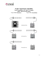
Page 11: ...10 Proper Yagi Antenna installation Cable available in 30 and 70 lengths Note Antenna orientation Yagi on Master Receiving Yagi on Slave Transmitting...

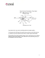
Page 12: ...o come out the front end of the antenna e g where you point the antenna is where 90 of the RF signal is transmitted Typical distance for properly aligned vertical Yagi to Yagi antennas is from 3000 to...

Page 13: ...sy locations or material that can hinder RF such as metal siding Tips on smaller sites such as historical homes banks churches etc Place on the Control Panel Place on the slave of the Repeater Tips on...

Page 14: ...ally Third Zone The Tandem feature allows 301s to be programmed to activate each other based on zone programming When two or more 301s share the same number in their zone programming i e zone 100 with...

Page 15: ...splayed If notification appliance s have been programmed and are activated they will remain activated until the Signal Silence button is pressed At this time the Control Panel can be reset by pressing...

Page 16: ...displayed To acknowledge the event press the Supervisory Ack button This will silence the internal horn but the condition s will remain displayed Pressing the Reset button will put the CP 3000A back...

Page 17: ...o digits of the repeater ID on the signal survey screen Place the repeater where the CP 3000A DA would be installed and take the fast to the first probable repeater location Press Signal Silence to pe...

Page 18: ...form a functional walk test on an installed network you will first need to enroll the FAST to the CP 3000A DA This will create a Checksum Bad trouble on the panel and on any WRA 3 Annunciators install...

Page 19: ...llowing partially load the battery in the battery socket Placing the magnet next to the vertical post from the chamber cover to the base above the test switch hole push the battery in If you have the...

Page 20: ...4 respectively 4 10K EOL Resistors 3 on Alarm Zones A B C 1 on Trouble Contact 1 Connection from CP 3000A Trouble Input to Keltron Trouble Output The Dialer Power Supply should be set to 24 Volts cha...

Page 21: ...20...

Page 22: ...rt number in the Keltron Software and in your PC s device manager verify change to the matching Port Number For example if the Keltron is using COM port 14 make sure your PC is communicating through p...

Page 23: ...125 ma Standby DC power 26 ma Alarm DC power 48 ma RB 10 to 40 relay box Standby AC power use AR 3A values as change is negligible Alarm AC power add 10 ma to AR 3A values per relay board Standby DC...

Page 24: ...ed 10 10 8 2 Bypass Mode A visible indicator shall be provided to indicate when the controller is in bypass mode 10 10 8 3 Variable Speed Pressure Limiting Control Overpressure Visible indication shal...

Page 25: ...9 3 6 Audible fire alarm signals shall meet the performance requirements of 18 4 3 and 18 4 5 29 3 7 When visible appliances are provided they shall meet the requirements of Section 18 5 Since hearing...

Page 26: ...en ambient conditions prohibit installation of automatic smoke detection automatic heat detection shall be permitted NFPA 72 2007 4 4 5 Protection of Fire Alarm System In areas that are not continuous...

Page 27: ...ll create a checksum bad trouble Test Failure On power up if the unit is not able to connect to a Network it will display a Test Failure trouble To clear this trouble press and hold ACK Step Signal Si...

Page 28: ...SIte Device 8 Once the file has been created import it by clicking on Import File a preview window will pop up click on Proceed and then click on Done 9 If the CP 3000DA panel you are monitoring has a...

Page 29: ...as indicated in the diagrams Figure 1 and Figure 2 at the end of the document depending upon whether you do or do not have an External Dialer 19 If your COM Port is not COM1 change the COM port on the...

Page 30: ...tails on how to configure remote monitoring Activity Reports 1 To be able to print out reports you must first download and install ActivityReports msi 2 Once it is installed Double Click on Activity R...

Page 31: ...s and system messages etc with this software Imports background images configures the COM port etc System Monitor CGSysMon exe This software attaches the COM port on the PC to the serial port on the C...

Page 32: ...ler data stream the Dialer Interface must be enabled on the CP 3000DA panel Log into the CP 3000DA panel Press Program scroll down to CP 3000DA Setup and press Enter Scroll down to Dialer Setup and pr...

Page 33: ...aler Trouble Input Figure 2 Hardware Setup With External Keltron Dialer Connection Diagram for CWSite when using an External Dialer CWSI P N MOD DE9MF 2WIRE DE9M DE9F Jumper Box Included in CWSite Cab...

Page 34: ...test the communications in Demo mode prior to receiving the license file and test some devices 14 Configure your com port on the CWSite PC that will be used on the job site Multiple Jobs Detail Notes...

Page 35: ...tware on the job site pc if it is different than COM1 Use the Configuration Manager tool to change the COM port Enable the Dialer Serial Data Stream on the CP 3000DA Panel Start the System Monitor pro...

Reviews: