I.L. 29C171
Page 5
Effective 3/98
rectly installed. If UVR and intermediate plunger appear
to be properly installed and problem persists, contact
Cutler-Hammer.
WHEN INSTALLING CIRCUIT BREAKER MAIN
COVER, MAKE SURE THAT ALL INTERNAL PARTS
ARE IN PLACE:
·
SLIDING HANDLE BARRIER IS POSITIONED SO
THAT THE HANDLE OPENING IS ALIGNED WITH
THE HANDLE.
·
ALL LEADS ARE CLEAR OF THE COVER.
2--11. With circuit breaker handle in the TRIPPED posi-
tion and accessory pigtail leads (if used) routed as
required, install circuit breaker covers. Secure
with pan-head screws. Torque to 20-22 lb-in.
(2.26-2.49 N.m.)
2-12. Remove and discard UL listing label on LDB cir-
cuit breakers only.
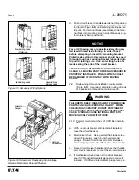
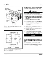
2-13. Place accessory labels (supplied with kit) on cir-
cuit breaker (see Figure 2-7).
2-14. Where practical and after taking all necessary
safety precautions, apply rated voltage to UVR.
Reset and close circuit breaker. Confirm that cir-
cuit breaker trips when voltage is removed.
2-15. Install circuit breaker.
Accessory labels show connection diagram for UVR
contacts. Pigtail leads are color coded orange and
brown.
2-16. Connect UVR as required (see Figure 2-8).
Cutler-Hammer assumes no responsibility for malfunc-
tioning accessories installed improperly by the cus-
tomer.
!
CAUTION
NOTICE
Figure 2-7 Preferred Mounting Locations for Accessory
Nameplate Labels
Figure 2-8 Undervoltage Release Mechanism (Handle
Reset) Connection Diagram
Terminal Block
Connection Diagram
Label (When Used)
Modification
Label
Accessory
Identification
Label
Pigtail
Connection
Diagram
(When Used)
Overcurrent Protection
(Supplied by Customer
When Required)
Overcurrent Protection
(Supplied by Customer
When Required)
Monitored
Voltage
Monitored
Voltage
Orange
Brown
UV1
UV2
UVR
UVR
Pigtail Leads
Terminal Block

