

I.L. 29C171
Page 3
Effective 3/98
To install UVR, circuit breaker operating mechanism
must be in tripped position.
Molded case switch trip units are not equipped with a
Push-to-Trip button. For molded case switches, omit
step 2-3.
2-2.
Disconnect and remove circuit breaker from instal-
lation and terminal connections.
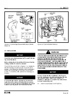
2-3. Press PUSH-TO-TRIP button to trip operating
mechanism, and check handle moves to trip posi-
tion with white colored indicator visible in
escutcheon window.
2-4.
Remove circuit breaker cover screws and covers.
2-5.
For high instantaneous trip-type (catalog suffix K
designation) molded case switches, find recessed
hole in either of the trip unit outer poles (Figure 2-
2). Push intermediate plunger supplied with UVR
in one hole to trip the molded case switch.
Remove plunger to prevent it falling out of
recessed hole in trip unit and into molded case
switch mechanism.
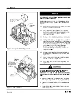
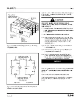
2-6.
Remove interphase barrier between accessory
mounting cavity and operating mechanism (see
Figure 2-3).
2-7.
Install replacement interphase barrier (supplied
with kit) in base (see Figure 2-3).
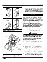
2-8.
Install UVR as described in following steps (see
Figure 2-4).
IF UVR IS REMOVED FROM CIRCUIT BREAKER,
INTERMEDIATE PLUNGER MUST ALSO BE
REMOVED. FAILURE TO REMOVE THE INTERMEDI-
ATE PLUNGER CAN RESULT IN EQUIPMENT DAM-
AGE.
a.
Remove barrier from trip unit accessory mounting
slots in pole bing used for accessory (Figure 2-2).
b.
Position intermediate plunger in trip unit (Figure 2-
2).
c.
Press intermediate plunger into recess in trip unit
and hold in position.
NOTICE
Figure 2-3 Interphase Barrier Replacement
Figure 2-4 UVR Installation
!
WARNING
Remove
Interphase
Barrier
Replacement Barrier
Supplied with UVR
Switch Kit
UVR Plug-in
Module
UVR Reset Lever in
Slot in Interphase
Barrier in Front of
Handle Arm
Interphase
Barrier


