I.B. 29C891B
Page 41
Effective 11/98
and time settings in keeping with system coor-
dination requirements.
Step 7:
If the system is utilizing one or more Breaker
Interface Modules or is network connected
through IMPACC, verification of circuit breaker
addresses and protective/ monitoring criteria
can be accomplished using a Breaker Interface
Module or remote computer. As required, refer
to Instruction Book 29C893 to review the use
of the Breaker Interface Module or Instruction
Book 29C890 for an overview of the complete
Digitrip OPTIM Trip Unit System, including
IMPACC communications.
4-3.2 INITIAL POWER APPLICATION
a. Apply system power and observe individual trip units
and/or other system monitoring devices, such as the
Breaker Interface Module or remote computer.
b. The green
Unit Status
LED should blink if either
(Figures
2-4
and
2-10
):
1.
The circuit breaker current in at least one
phase exceeds 20% of the installed rating
plug value
(or)
2.
Auxiliary power is supplied to the circuit
breaker.
The red transmit LED will blink whenever the trip unit
is communicating on the IMPACC Network.
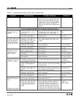
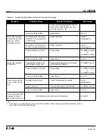
c. Should what appears to be a problem occur, refer to
the Troubleshooting Guide (Table
5.1
) of this manu-
al. For additional troubleshooting assistance, refer to
the Troubleshooting Guides in the OPTIMizer Hand
Held Programmer and/or the Breaker Interface
Module instruction books (I.B. 29C892 and I.B.
29C893 respectively). For further assistance, consult
Cutler-Hammer.
4-4 TESTING
Section 3-5 provides details associated with testing
OPTIM Trip Units and circuit breakers equipped with
OPTIM Trip Units. It is recommended that Section 3-5
be read first. In addition, follow the testing instructions
presented in the OPTIMizer Hand Held Programmer
instruction book (I.B. 29C892) or the Breaker Interface
Module instruction book (I.B. 29C893). Testing can also
be performed using a remote computer over the
IMPACC system.
Summary of Contents for Digitrip OPTIM 1050
Page 7: ......


