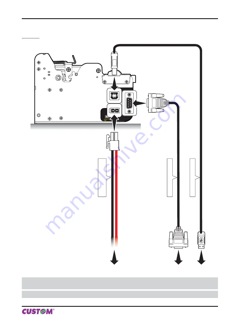
Custom Engineering B202H User Manual Download Page 29

3.3 Connections

KPM150H

RS232

POWER SUPPLY

USB

Serial standard cable

USB standard cable

Power Supply cable

(supplied)

WARNING: In some using conditions, we recommend the installation of a ferrite core on the power supply 
cable and on the serial cable.

NOTE:

 If RS232 and USB connectors are inserted, communication port is USB.

3. INSTALLATION 

User manual

  KPM150H-AERO  29

Summary of Contents for B202H

Page 1: ...OEM AIRPORT KPM150H KPM150H B202H B202H USER MANUAL...

Page 2: ......

Page 3: ...is an easily acces sible outlet with a capacity of no less than 10A closely to where the device is to be installed Periodically perform scheduled mainte nance on the device to avoid dirt build up that...

Page 4: ......

Page 5: ...sor position 40 4 3 Turning on the device 46 4 4 Paper roll insertion 48 5 CONFIGURATION 55 5 1 Configuration mode 55 5 2 Setup report 58 5 3 Printer status 59 5 4 Printer parameters 60 5 6 Calendar c...

Page 6: ...11 ADVANCED FUNCTIONS 105 11 1 File sharing 105 11 2 Drivers installation 105 11 3 Setup 106 INDEX 6 KPM150H AERO User manual...

Page 7: ...ce and its accessories 8 ACCESSORIES description and installation of the available accessories for the device 9 ALIGNMENT information required for managing the paper alignment 10 TECHNICAL SERVICE inf...

Page 8: ...1 INTRODUCTION 8 KPM150H AERO User manual...

Page 9: ...in the future Make sure that all the components illustrated below are present and that there are no signs of damage If there are contact Customer Service KPM150H 1 Installation instructions sheet 2 Po...

Page 10: ...oam packing shell 8 Power supply 9 Box Open the printer packaging Remove the upper packing frame content and remove the upper packing frame Take out the printer Keep the box trays and packing material...

Page 11: ...sis 6 Paper outfeed 2 Cutter unit 7 LINE FEED key 3 Hook of printing head group 8 FORM FEED key 4 Printing head group 9 Status led 5 Paper input 10 Lever of paper mouth guide adjustable STATUS NEAR PA...

Page 12: ...2 UHF RFID antenna 8 Status led 3 Printing head group 9 FORM FEED key 4 Hook of printing head group 10 LINE FEED key 5 Cutter unit 11 Paper outfeed 6 Printer chassis STATUS NEAR PAPER END LF FF R S 2...

Page 13: ...ssis 6 Paper outfeed 2 Cutter unit 7 LINE FEED key 3 Hook of printing head group 8 FORM FEED key 4 Printing head group 9 Status led 5 Paper input 10 Lever of paper mouth guide adjustable 5 1 2 3 4 6 1...

Page 14: ...er cover 5 FORM FEED key 2 Paper output 6 Hook of printing head group 3 Status led 7 Lever of paper mouth guide adjustable 4 LINE FEED key 8 Paper input LF FF 6 7 8 LF FF LF FF 1 3 2 4 5 2 DESCRIPTION...

Page 15: ...ter cover 6 Hook of printing head group 2 Paper output 7 UHF RFID antenna 3 Status led 8 UHF RFID control board 4 LINE FEED key 9 Paper input 5 FORM FEED key LF FF LF FF 1 3 2 4 5 FF LF 6 9 8 7 2 DESC...

Page 16: ...3 Printer components connectors views KPM150H 1 USB connector 2 RS232 connector 3 Power Supply connector 4 Connector for external near paper end sensor 1 2 3 4 2 DESCRIPTION 16 KPM150H AERO User manua...

Page 17: ...KPM150H models with rear connectors 1 RS232 connector 2 USB connector 3 Power Supply connector 4 Connector for external near paper end sensor 1 2 3 4 2 DESCRIPTION User manual KPM150H AERO 17...

Page 18: ...B202H 1 Connector for external near paper end sensor 2 RS232 connector 3 USB connector 4 Power Supply connector 5 ON OFF key LF FF 1 2 3 4 5 2 DESCRIPTION 18 KPM150H AERO User manual...

Page 19: ...sparence sensor and notch NEA R PA PER EN D FF LF STATUS 2 5 1 1 3 4 NOTE For ease of reference for some models is represented only the printer group without the external plastic chassis PRODUCT LABEL...

Page 20: ...m the FONT TEST LF FF LF FF Hold down Hold down enter the SETUP MODE enter the Clock SETUP skip the SETUP mode LF FF Fast push LF FF LF FF Fast push Fast push modify parameter next parameter LF FF LF...

Page 21: ...by LF FF Hold down LF FF Fast push LF FF STANDBY Fast push x3 sec Moves the motor backwards and releases the paper to be removed Perform an alignment to next ticket Reset the printer 2 DESCRIPTION Use...

Page 22: ...ON NO ERROR GREEN COMMUNICATION STATUS 1 x RECEIVING DATA 2 x RECEIPT ERRORS PARITY FRAME ERROR OVERRUN ERROR 3 x COMMAND NOT RECOGNIZED 4 x COMMAND RECEIPT TIME OUT 5 x NEAR PAPER END YELLOW RECOVER...

Page 23: ...FRAME ERROR OVERRUN ERROR 3 x COMMAND NOT RECOGNIZED 4 x COMMAND RECEIPT TIME OUT 5 x NEAR PAPER END VIOLET RECOVERABLE ERROR 2 x PRINT HEAD OVER HEAT 3 x PAPER END 4 x PEPER JAM 5 x POWER SUPPLY VOL...

Page 24: ...2 DESCRIPTION 24 KPM150H AERO User manual...

Page 25: ...tening KPM150H The printer is provided with four fixing holes placed on lateral side see following figure To fasten the printer on a panel use four M3 screws 102 120 13 7 3 7 140 3 INSTALLATION User m...

Page 26: ...ectors The printer is provided with four fixing holes placed on lateral side see following figure To fasten the printer on a panel use four M4 screws 10 58 20 105 23 4 N 4 M Fixing point 3 INSTALLATIO...

Page 27: ...PE wiring Fixing screw M3 MATERIAL INCLUDED MATERIAL NOT INCLUDED For the assembly procedure proceed as follows 1 Fix the near paper end sensor board to the support using an M3 screw not included For...

Page 28: ...2 Connect the wiring coming from the near paper end sensor board at the connector shown in figure NPE wiring 3 INSTALLATION 28 KPM150H AERO User manual...

Page 29: ...cable Power Supply cable supplied WARNING In some using conditions we recommend the installation of a ferrite core on the power supply cable and on the serial cable NOTE If RS232 and USB connectors a...

Page 30: ...andard cable Power Supply cable supplied WARNING In some using conditions we recommend the installation of a ferrite core on the power supply cable and on the serial cable NOTE If RS232 and USB connec...

Page 31: ...supply cable 24Vdc supplied B202H power supply supplied WARNING In some using conditions we recommend the installation of a ferrite core on the serial cable NOTE If RS232 and USB connectors are insert...

Page 32: ...y cable The following figures show the connector pinout of the power supply cable for the device Power supply cable for KPM150H Female Molex connector series 5557 no 39 01 3022 GND 24 V 1 1 4 4 2 2 3...

Page 33: ...esponds to a voltage level of between 3Vdc and 15Vdc and logic value 1 corresponds to a voltage level of between 3Vdc and 15Vdc NOTE DEVICE PC connection The following pictures shows an example of con...

Page 34: ...er supply cable The following figures show the connector pinout of the power supply cable for the device Power supply cable for KPM150H Female Molex connector series 5557 no 39 01 3022 GND 24 V 1 1 4...

Page 35: ...esponds to a voltage level of between 3Vdc and 15Vdc and logic value 1 corresponds to a voltage level of between 3Vdc and 15Vdc NOTE DEVICE PC connection The following pictures shows an example of con...

Page 36: ...onnector J2 1 GND 2 24 Vdc 3 GND 4 Frame GND Warning Respect power supply polarity 1 1 4 4 2 2 3 3 USB INTERFACE Female USB type B connector J4 1 USB VBUS out 2 PD 0 3 PD 0 4 GND SH1 SHIELD SH2 SHIELD...

Page 37: ...esponds to a voltage level of between 3Vdc and 15Vdc and logic value 1 corresponds to a voltage level of between 3Vdc and 15Vdc NOTE DEVICE PC connection The following pictures shows an example of con...

Page 38: ...Driver for Linux 32 64bit Follow the instruction get back on the README TXT file you can find it in the software package downloaded in advance Android SDK for CustomAndroidAPI Extract the zipped folde...

Page 39: ...cated at the paper infeed opening as shown in the following figure To manage paper width from 20mm to 54mm press the lever of paper mouth guide and move it in according to type of paper used see follo...

Page 40: ...the non heat sensitive side Notch B Mark Position Bottom Notch positioned on the heat sensitive side Notch B Mark Position Top Hole between tickets or gap between labels Notch B Mark Position Transpa...

Page 41: ...just the paper width see previous paragraphs 3 Open the printer cover to the vertical up position ATTENTION Do not touch the head heating line with bare hands or metal objects Do not perform any opera...

Page 42: ...oving the sensor inside its sliding guide 4 Move the lower sensor to the desired position using a small screwdriver or a pencil 5 Close the printer cover 6 Insert the plastic upper cover and lower it...

Page 43: ...e side Notch B Mark Position Bottom Notch positioned on the heat sensitive side Notch B Mark Position Top Hole between tickets or gap between labels Notch B Mark Position Transparence STATUS NEAR PAPE...

Page 44: ...d group using the hook A located on the cover ATTENTION Do not touch the head heating line with bare hands or metal objects Do not perform any operation inside the printer immedi ately after printing...

Page 45: ...ng the sensor inside its sliding guide 4 Move the lower sensor to the desired position using a small screwdriver or a pencil 5 Close the printing head group 6 Insert the plastic upper cover and lower...

Page 46: ...upplied model with rear connectors 2 Connect the power supply cable to the printer connector see par 3 3 standard model 3 The green led turns on and the printer is ready STATUS NE AR PAPER EN D FF LF...

Page 47: ...ower supply cable 24Vdc to the connector of the printer see par 3 3 LF FF Power Supply VIn 24Vdc Press the ON OFF key 4 ON OFF LF FF Power supply cable 24Vdc supplied 3 Connect the power supply cable...

Page 48: ...rd models 1 Adjust the paper width see previous paragraphs 2 Adjust the notch sensor position see previous paragraphs 3 Insert the paper edge into the feed slot place the paper roll so that it unrolls...

Page 49: ...rd models 2 Place the cover on a even surface 3 Adjust the paper width see previous paragraphs 4 Open the paper compartment cover LF FF 1 Lift the plastic cover LF FF LF FF 4 OPERATION User manual KPM...

Page 50: ...f notch see previous paragraphs 7 Wait for the paper to load automatically 6 Insert the paper 8 Insert the plastic upper cover and lower it to close the printer VROOM ATTENTION Make sure the cut is st...

Page 51: ...ous paragraphs 2 Insert the paper edge into the feed slot place the paper roll so that it unrolls correctly ATTENTION Make sure the cut is straight 3 Wait for the paper to load automatically STATUS NE...

Page 52: ...er 2 Place the cover on a even surface 4 Adjust the position of lower mobile sensor of notch see previous paragraphs 1 Lift the palstic cover FF LF FF LF 3 Open the paper compartment cover 4 OPERATION...

Page 53: ...for the paper to load automatically 7 Insert the plastic upper cover and lower it to close the printer VROOM ATTENTION Make sure the cut is straight 5 Insert the paper 4 OPERATION User manual KPM150H...

Page 54: ...4 OPERATION 54 KPM150H AERO User manual...

Page 55: ...e printer proceed as follows KPM150H 1 During power up hold down the LINE FEED key while the wiring is plugged into the power supply connector of the printer standard model model with rear connectors...

Page 56: ...device prints a SETUP report PRINTER SETTINGS PRINTER TYPE KPM150H Barcode Reader Not present RFID Module Not present PRINTING HEAD TYPE SHECT56 INTERFACE RS232 PROGRAM MEMORY TEST OK K DYNAMIC RAM TE...

Page 57: ...mCODE code rel 1 00 UCODE code rel 1 00 DCODE code rel 2 00 CPLD rel 1 10 NOTE During power up if the LINE FEED key is held down the printer enters the auto test routine and prints out the setup repo...

Page 58: ...09 30 Printer Emulation SERVICE RS232 Baud Rate 9600 bps RS232 Data Length 8 bits chr RS232 Parity None USB Mass Storage Enabled USB Address Number 0 Print Mode Normal Speed Quality High Speed Paper T...

Page 59: ...OK appears if functioning and NOT OK if faulty DYNAMIC RAM TEST the message OK appears if functioning and NOT OK if faulty EEPROM TEST the message OK appears if functioning and NOT OK if faulty CUTTE...

Page 60: ...rface RS232 PARITY Bit for the parity control of the serial interface None D parity bit omitted Even even value for parity bit Odd odd value for parity bit NOTE Parameter valid only with serial interf...

Page 61: ...ch by the notch sensor 20 D 50 80 30 60 90 40 70 NOTE If the Notch B Mark Position parameter is disabled this parameter is not printed USB VIRTUALCOM Setting of the USB port as a virtual serial port D...

Page 62: ...l part and of the sign VERTICAL SCALE SIGN Sign setting D positive percentage value negative percentage value VERTICAL SCALE x 10 Setting the digit for tens 0 D 4 8 1 5 9 2 6 3 7 VERTICAL SCALE x 1 Se...

Page 63: ...TE For example to set the presenter offset to 10 mm modify the parameters as follows Presenter Offset Signum Presenter Offset mm x 10 1 Presenter Offset mm x 1 5 ALIGN TICKET This parameter defines wh...

Page 64: ...ough the communication port For example for every 8 charac ters received the hexadecimal and corresponding ASCII codes are printed out if the characters are underlined the receive buffer is full Shown...

Page 65: ...Pressing LINE FEED key to modify the value of the highlighted digit every single LINE FEED key pressure increases of 1 his value Once the value 9 is reached the counting starts again from 0 Pressing...

Page 66: ...5 CONFIGURATION 66 KPM150H AERO User manual...

Page 67: ...er to the vertical up position 2 Remove the damaged paper and check the presence for paper scraps in the printer ATTENTION Do not let water or other liquids get inside the device Do not insert any kin...

Page 68: ...sure the cut is straight 4 Insert the not damaged paper edge into the feed slot place the roll so that it unrolls correctly 5 Wait for the paper to load automatically VROOM 6 MAINTENANCE 68 KPM150H AE...

Page 69: ...rtment cover LF FF 4 Close the paper compartment cover 3 Remove the damaged paper and check the presence for paper scraps in the printer ATTENTION Do not let water or other liquids get inside the devi...

Page 70: ...d slot place the roll so that it unrolls correctly 7 Insert the plastic upper cover and lower it to close the printer 6 Wait for the paper to load automatically VROOM ATTENTION Make sure the cut is st...

Page 71: ...S Cutter Use compressed air Paper path Use compressed air or tweezers Sensors Use compressed air EVERY 6 MONTHS OR AS NEEDED Case Use compressed air or a soft cloth For specific procedures see the fol...

Page 72: ...TION Do not touch the head heating line with bare hands or metal objects Do not perform any operation inside the printer immedi ately after printing because the head and motor tend to become very hot...

Page 73: ...hol solvents or hard brushes Do not let water or other liquids get inside the machine ON Alcohol solvent cohol solve ATTENTION Do not touch the head heating line with bare hands or metal objects Do no...

Page 74: ...sition ATTENTION Do not touch the head heating line with bare hands or metal objects Do not perform any operation inside the printer immedi ately after printing because the head and motor tend to beco...

Page 75: ...ting line with bare hands or metal objects Do not perform any operation inside the printer immedi ately after printing because the head and motor tend to become very hot ATTENTION Do not use alcohol s...

Page 76: ...ration inside the printer immedi ately after printing because the head and motor tend to become very hot ATTENTION Do not use alcohol solvents or hard brushes Do not let water or other liquids get ins...

Page 77: ...h CASE 1 Disconnect the power supply cable ATTENTION Do not use alcohol solvents or hard brushes Do not let water or other liquids get inside the machine ON Alcohol solvent cohol solve STATUS NEAR PAP...

Page 78: ...r 6 Connect the printer to the PC using a serial cable see par 3 2 7 Switch ON the printer 8 Start the software UPGCEAERO 9 Select the update file PSW location 10 Select the serial communication port...

Page 79: ...see par 3 2 7 Switch ON the printer 8 Start the software UPGCEAERO 9 Select the update file PSW location 10 Select item USB and then select the USB device among those proposed e g KPM150H C VKP80III P...

Page 80: ...6 MAINTENANCE 80 KPM150H AERO User manual...

Page 81: ...arcode Interleaved 2 of 5 Industrial 2 of 5 CODE39 CODE128 Interleaved 2 of 5 including check digit Industrial 2of 5 including check digit CODE39 including check digit CODE128 including check digit EA...

Page 82: ...A Power 60 W ENVIRONMENTAL CONDITIONS Operating temperature from 0 C to 50 C Relative humidity from 10 to 85 w o condensation Storage temperature from 20 C to 70 C Storage humidity from 10 to 90 NOTE...

Page 83: ...PECIFICATIONS Length 171 mm Height with printer cover closed 122 mm Width 114 mm Weight 1850 g NOTE Referred to model without paper roll 122 171 175 5 84 105 119 99 5 88 86 114 120 13 140 102 7 3 7 7...

Page 84: ...KPM150H models with rear connectors 176 184 5 122 80 1 96 88 4 8 88 86 1 7 SPECIFICATIONS 84 KPM150H AERO User manual...

Page 85: ...KPM150H models with stop device ticket dimensions in mm optional 171 175 5 84 105 119 122 85 23 30 105 2 114 99 5 88 7 3 7 102 75 120 13 140 7 SPECIFICATIONS User manual KPM150H AERO 85...

Page 86: ...KPM150H models with ejecter retention ticket dimensions in mm optional 85 122 171 175 5 84 105 119 96 8 23 20 2 7 3 7 102 75 120 13 140 114 72 99 5 88 7 SPECIFICATIONS 86 KPM150H AERO User manual...

Page 87: ...L SPECIFICATIONS Length 194 mm Height with printer cover closed 155 mm Width 133 2 mm Weight 2800 g NOTE Referred to model without paper roll 133 2 108 55 3 194 152 104 3 7 SPECIFICATIONS User manual...

Page 88: ...B202H models with paper roll holder dimensions in mm optional 104 3 133 2 170 194 155 39 1 55 108 5 3 7 SPECIFICATIONS 88 KPM150H AERO User manual...

Page 89: ...B202H models with ticket tray dimensions in mm optional 31 6 70 31 6 152 194 363 5 3 4 21 4 133 2 108 55 3 7 SPECIFICATIONS User manual KPM150H AERO 89...

Page 90: ...ly dimensions cod 963GE020000003 optional for KPM150H supplied with B202H Length 127 mm Height 35 5 mm Width 56 mm 35 5 24V GND N C 1 2 3 AC INLET 56 127 DC OUTPUT WIRE 7 SPECIFICATIONS 90 KPM150H AER...

Page 91: ...R SUPPLY for technical specifications see paragraph 7 1 and paragraph 7 4 963GE020000003 STOP DEVICE TICKET KPM150H 970AN010000001 EJECTER RETENTION TICKET KIT KPM150H only for models with control boa...

Page 92: ...B202H see paragraph 8 1 97000000000200 BRACKET PRINTER B202H see paragraph 8 2 21100000001060 ADDITIONAL WIRING NEAR PAPER END B202H 26300000000519 ADDITIONAL NEAR PAPER END SENSOR BOARD B202H 813000...

Page 93: ...plied as an accessory The kit makes it possible to contain tickets from 20mm to 54mm max The kit includes 1 Chute collect tickets 2 N 2 fastening screws 2 1 Assembly instructions 1 Remove the frontal...

Page 94: ...t cover in the two upper holes using the two M3x6 screws supplied in the kit LF FF 2 Move the chute collect tickets to the printer s front cover so that it is in contact with the printer LF FF 8 ACCES...

Page 95: ...the bracket to the bottom of the printer using four M3x6 screws not supplied The kit includes 1 Connecting bracket printer Connecting bracket printer MATERIAL NOT INCLUDED MATERIAL INCLUDED Fixing scr...

Page 96: ...F FF 3 Put the printer with the bracket mounted on top of another 2 Attach the bracket to the bottom of the printer using four M3x6 screws not included with the kit 8 ACCESSORIES 96 KPM150H AERO User...

Page 97: ...26900000000005 supplied as accessory for connecting the printer to the external power supply unit cod 963GE020000003 optional Assembly instructions Connect the adapter cable to the power supply unit a...

Page 98: ...8 ACCESSORIES 98 KPM150H AERO User manual...

Page 99: ...sor considering that the light is reflected by the white paper and absorbed by the black mark To use tickets with holes or labes with gap it is possible to use the same sensors as transparence sensors...

Page 100: ...Position during the Setup procedure see chapter 5 and set the correct value of this parameter as described in the following table SENSOR USED see following figure VALUE OF THE NOTCH B MARK POSITION P...

Page 101: ...ecution of the function of paper characterization Characterize Paper and the change of the Notch B Mark Threshold parameter which represents the detection threshold of the notch Choosing the Yes value...

Page 102: ...hile passing the paper between two holes and presents a variation at each hole In this case the optimal value for the Notch B Mark Threshold parameter is placed about half of the variation Notch B Mar...

Page 103: ...Find the product and the firmware label located on the bottom of the printer for B202H 1 Find the product and the firmware label located on the side of the printer for KPM150H product code 14 digits X...

Page 104: ...AD TYPE SHECT56 INTERFACE RS232 PROGRAM MEMORY TEST OK K DYNAMIC RAM TES ST T OK OK KPM150H AERO ST SCODE code rel 1 00 BCODE code rel 1 00 FCODE code rel 1 00 mCODE code rel 1 00 UCODE code rel 1 00...

Page 105: ...ing from Mass Storage The relative parameter should be enabled during the configuration process see chapter 5 FILE SHARING FROM MASS STORAGE USB USB 11 2 Drivers installation It is possible to install...

Page 106: ...t value change the numeric value with the symbol D The Setup ini file permits the configuration of the following parameters PRINT PRINTER EMULATION 0 1 0 SERVICE 1 BTP PRINT MODE 0 1 0 Normal 1 Revers...

Page 107: ...Even 2 Odd USB MASS STORAGE 0 1 0 Disabled 1 Enabled USB ADDRESS NUMBER 0 1 2 3 4 5 6 7 8 9 0 0 4 4 8 8 1 1 5 5 9 9 2 2 6 6 3 3 7 7 USB VIRTUALCOM 0 1 0 Disabled 1 Enabled NOTE For parameters descrip...

Page 108: ...11 ADVANCED FUNCTIONS 108 KPM150H AERO User manual...

Page 109: ......

Page 110: ......

Page 111: ......

Page 112: ...200000003400 Rev 1 50 www custom biz CUSTOM ENGINEERING S p A World Headquarters Via Berettine 2 43010 Fontevivo Parma ITALY Tel 39 0521 680111 Fax 39 0521 610701 info custom biz www custom biz All ri...

Reviews: