15
INITIAL SET UP, LUBRICATION AND PLC RESET
Initial Setup
Check to be certain that the motor rotates in the direction of the arrow shown
on the motor housing. If motor rotation is opposite of the direction of the
arrow, reverse any two hot wires in the electrical plug.
Damage to the pump can result if the motor does not rotate in the correct
direction.
Check the oil level in the sight glass on the front of the tank. 50 U.S. gallons
of ISO 46 hydraulic oil are required to completely refi ll the tank.
Oil can be drained from either of the two ports at the bottom of the tank.
An additional oil cooler, while not normally required, can be plumbed into the
two ports at the rear of the tank.
Lubrication
Lubricate the crimping head after each 100 crimping cycles or at the start of
each shift if the crimper is used in a production setting.
Bring the master dies to the fully closed position, and lubricate the master
dies through the 8 holes in the protective plates as illustrated.
With the dies still in the fully closed position lubricate the fi ttings visible through
the 2 bottom lubrication holes in the protective plate of the crimper.
Use only a high quality grease. Failure to do so may result in damage to the
wearing surfaces.
PLC Reset Procedure
The PLC (Programmable Logic Controller)
requires a relatively constant source of electrical
power. Power surges, outages or drops in power
can cause the PLC to lose its settings. This may
result in missing or misplaced information on the
controller screen
.
Resetting the PLC to its original
settings is a simple procedure
• Turn the main power switch to OFF.
• Open the front of the Control Panel.
• Power up the crimper from the main power switch. The crimper must be
powered on during the PLC reset procedure.
• Move the three position toggle switch on top of the PLC right to the STOP
position and then left to the RUN position.
• Return the toggle switch to the center TERM position.
• Repeat for the other PLC Unit.
• Turn the main power switch to OFF and replace the front panel.
• The PLC and the crimper should now operate normally.
Summary of Contents for CC1200
Page 1: ...1 CC1200 CRIMPER OPERATORS MANUAL WITH ACTTM CONTROLLER ...
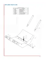
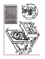
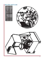
Page 18: ...18 EXPLODED PARTS VIEW ...
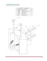
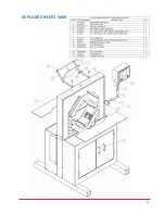
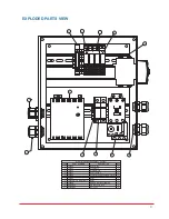
Page 19: ...19 EXPLODED PARTS VIEW ...
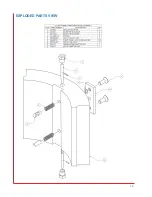
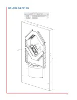
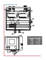
Page 20: ...20 EXPLODED PARTS VIEW ...
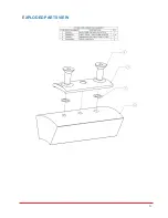
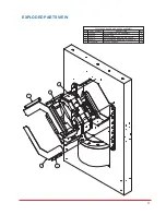
Page 21: ...21 EXPLODED PARTS VIEW ...
Page 23: ...23 EXPLODED PARTS VIEW ...
Page 24: ...24 EXPLODED PARTS VIEW ...


