SR
SL
FR
FL
CEN
SW
SPEAKERS IMPEDANCE 4
8
120V~60Hz
120V~60Hz
DVD5045
120V ~60Hz
150W
COAXIAL
S-VIDEO
VIDEO OUT
OPTICAL
C US
LISTED
Audio/Video Apparatus
E
2 2 1 3 3 8
5 8 W J
DVD RECEIVER
DVD5045
DVD & AMPLIFIER SYSTEM
DVD/ CD/ MP3/ CD-RW/ HDCD/ JPEG
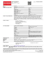
OPEN/CLOSE
1. POWER
Before plugging the power cord into the AC
outlet, check to make sure all of the connections
have been properly completed. When they
have been done, carefully plug power cord into
outlet.
Press the POWER button on the front panel
to power the unit.
When the unit is initially powered, a brief surge
of electricity may cause interference with other
electronic equipment on the same circuit. If this
occurs, connect the unit to an outlet on a
different circuit.
. /OPEN/CLOSE
Use this button to open and close the disc tray
while in DVD mode. It is disabled when another
signal source is used.
3. /MEMO
Use this button to stop play function while in DVD
mode.
While in the tuner mode, this button is used to
memory station.
2
FRONT AND BACK PANELS
1
2
6
5
8
3
4
7
Front Panel Functions
4.
/DOWN
While in the DVD status, you may press this
button for previous track.
While in the tuner mode, you may press this bu-
tton for radio down search.
5.
/UP
Button.
While in the DVD status, you may press this
button for next track. .
While in the tuner mode, you may press this bu-
tton for radio up search.
6. INPUT SIGNAL SOURCE
Use this button to select the proper input signal
source. (Note: The selected input will correspond to
the selected input terminal on the rear panel.)
7. VOLUME
Use this button to control the unit's volume. It
controls all six channels simultaneously.
8. /PRE/TUN
When in the Tuner mode, this button is used to
select preseting or tuning mode.
Use this button to begin play function while in
DVD mode.
Back Panel Functions
1. ANTENNA
Use to connect the provided indoor FM and
AM loop antennas.
2. AUX IN
Use to connect input for both auxiliary 1 and
2 music sources.
3. AUDIO OUT
Use to connect both the right and left channel
line outputs as well as subwoofer output.
4. VIDEO OUTPUT
5. OPTICAL OUTPUT
6. S-VIDEO OUTPUT
8. FRONT/MAIN
Use to connect the four terminals of the left
and right front or main speakers.
9. CENTER/SUBWOOFER
Use to connect the four terminals of the center
and subwoofer speakers.
10. COAXIAL OUTPUT
11. 120V/60Hz
This unit comes with an AC power cord. Be
sure its prongs are dry before plugging it into an
electrical outlet. Take caution not to overextend
the cord or walk on it.
12. COMPONENT VIDEO OUTPUT
7. REAR
Use to connect the four terminals of the left
and right surround sound speakers.
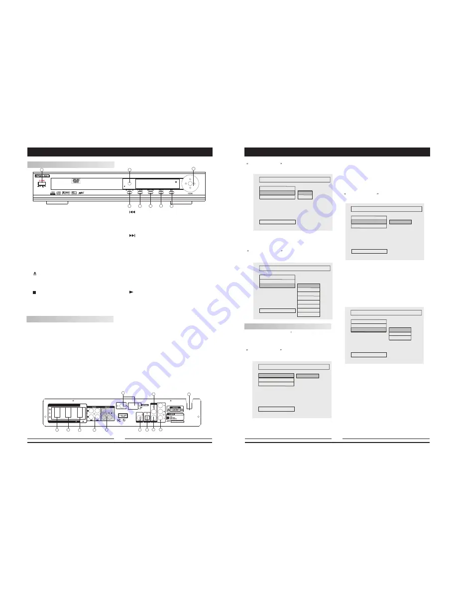
SYSTEM SETUP
3D PROCESSING PAGE
V SURR
ON
OFF
PRO LOGIC
REVERB MODE
AUDIO SETUP
V SURR
Virtual surround is set to ON or OFF.
REVERB MODE
Follow the operation instructions stated in
DVD menu setup
in combination with desired
option in the following figure.
3D PROCESS
ING PAGE
REVERB MODE
PRO LOGIC
REVERB MODE
AUDIO SETUP
V SURR
OFF
CONCERT
LIVING ROOM
HALL
BATHROOM
CAVE
ARENA
CHURCH
VIDEO SETUP
Video setup includes
brightness, contrast
and video output.
BRIGHTNESS
Follow the operation instructions stated in
DVD menu setup
in combination with desired
option in the following figure.
Press right arrow button to enter adjustment
mode; press up and down buttons to make
adjustment.
Press left arrow button to return to setup menu.
DVD menu setup
in combination with desired
option in the following figure.
VIDEO SETUP PAGE
BRIGTNESS
CONTRAST
VIDEO OUT
BRIGTNESS
MAIN PAGE
O
CONTRAST
Follow the operation instructions stated in
DVD menu setup
in combination with desired
option in the following figure.
VIDEO OUTPUT
Follow the operation instructions stated in
DVD menu setup in combination with desired
option in the following figure.
Press right arrow button to enter adjustment
mode; press up and down buttons to make
adjustment.
Press left arrow button to return to setup menu.
VIDEO SETUP PAGE
CONTRAST
BRIGTNESS
VIDEO OUT
CONTRAST
MAIN PAGE
O
VIDEO SETUP PAGE
SET VIDEO OUT
BRIGTNESS
CONTRAST
VIDEO OUT
MAIN PAGE
S-VIDEO
YUV
RGB
23
6
3
11
10
2
7
8
9
1
4
5
6
12