Parts List
DESCRIPTION
PART NUMBER
QTY
ITEM
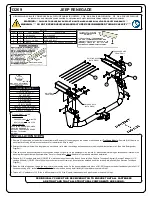
1/2" FISHWIRE
1_2 FISHWIRE
6
1
HEX FLANGE NUT
HFN 1213, GR8
6
2
CARRIAGE BOLT
1/2-13 x 1 3/4, GR8
6
3
.250 x 1.00 x 2.50" SQUARE HOLE SPACER
CM-SP10
8
4
GROSS LOAD CAPACITY WHEN USED AS A WEIGHT CARRYING HITCH: LBS. TRAILER WEIGHT & LBS. TONGUE WEIGHT.
WARNING: ALL NON-TRAILER LOADS APPLIED TO THIS PRODUCT MUST BE SUPPORTED BY 18050 STABILIZING STRAPS.
WARNING:
** FAILURE TO PROPERLY SUPPORT NON-TRAILER LOADS WILL VOID PRODUCT WARRANTY **
WARNING: *** DO NOT EXCEED VEHICLE MANUFACTURER'S RECOMMENDED TOWING CAPACITY ***
HITCH WEIGHT: LBS.
INSTALL TIME
PROFESSIONAL: MINUTES
NOVICE (DIY): MINUTES
INSTALL NOTES:
INSTALLATION STEPS
PERIODICALLY CHECK THIS RECEIVER HITCH TO ENSURE THAT ALL FASTENERS
ARE TIGHT AND THAT ALL STRUCTURAL COMPONENTS ARE SOUND.
3,500
525
37
30
JEEP RENEGADE
13269
60
1.125 in
-HOLE ENLARGEMENT REQUIRED
-FISHWIRE HARDWARE
-REVERSE FISHWIRE HARDWARE
-WELDNUT CLEANING
-NO DRILL
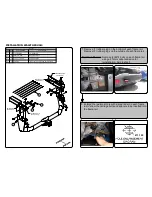
1. Remove (1) rubber plug on the bottom of each frame rail. Remove (2) rubber plugs on the outside of each frame rail.
Trailhawk Models:
Remove (3) M14 bolts on
each frame rail using a 21mm socket and save for reinstallation. Skip to step 5.
2. Enlarge the rearmost hole with a die grinder on each frame rail to allow the carriage bolts and spacers to be inserted into the frame rail. (See Hole Enlargement
Diagram.)
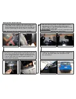
3. Clear away caulk as necessary near mounting holes using a utility knife. On the passenger side, remove (2) plastic screws retaining an access panel located in the
wheel well using an offset phillips screwdriver. Save for reinstallation.
Note:
Removal of rear wheels may ease installation.
4
.
Fishwire (2) 1/2" carriage bolts and (2) CM-SP10's into the holes on the outside of each frame rail (See Fishwire Technique Diagram). Reverse Fishwire (1) 1/2"
carriage bolt and (1) CM-SP10 into the hole on the bottom of each frame rail. Keep fishwires attached until hitch is raised into position (See Reverse Technique
Diagram.)
5. Raise the hitch into position, thread the fishwire into the mounting holes. On the bottom attachments, place a CM-SP10 spacer on the bolt and loosely install all 1/2"
flange nuts using a 3/4" socket.
Trailhawk Models:
Raise hitch and loosely install factory M14 hardware removed in Step 1.
6. Torque all 1/2" hardware to 110 ft.-lbs or M14 hardware to 135 ft-lbs. Reinstall access panel and plastic screws removed in Step 3.
DRIVER SIDE
FRAME RAIL
ENLARGE HOLE
(BOTH SIDES)
1
1
REMOVED M14 FLANGE NUT FROM BOM
5/19/2015
NDH
2
REVISED FOR TRAILHAWK TRIM
9/28/2015
NDH
REVISION HISTORY
REV
DESCRIPTION
DATE
APPROVED
PASSENGER SIDE
FRAME RAIL
4
2
3
TOOLS REQUIRED
RATCHET
TORQUE WRENCH
3/4" SOCKET
21mm SOCKET
8" EXTENSION
DIE GRINDER
UTILITY KNIFE
OFFSET SCREWDRIVER
UNIVERSAL JOINT SOCKET
SAFETY GLASSES
EXISTING HOLES
(BOTH SIDES)
Summary of Contents for 13269
Page 4: ......


