background image

16

17

ASSEMBLY INSTRUCTIONS

19

20

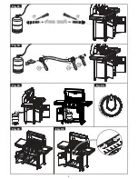
FOR PROPANE MODEL ONLY.

For natural gas model, follow step 20.

a. Position the 20 lb propane tank onto the bot-

tom shelf (EG), and secure using the bolt (F4)

(already attached) located on the underside of 

the bottom shelf, as shown in figure B.

b. Attach the regulator coupling nut to the LP 

cylinder valve.  

       ATTENTION:  For your families safety, do 

not attempt to light this BBQ until you have 

reviewed pages 4-7 of the Cuisinart

TM

 Safety 

& Care Manual.  All Safety and Leak test MUST 

BE PERFORMED BY THE END USER, prior to 

lighting this BBQ. 

B

       WARNING 

Do not store extra propane tanks within 

BBQ cart.

FOR NATURAL GAS MODEL ONLY.

Attach the natural gas hose (CB) to the side burner 

valve (CC) as shown. 

ATTENTION:  In order to complete installa-

tion of your Natural Gas BBQ a 1/2” or 3/8” 

adapter may be required to connect your 

BBQ’s Natural Gas hose to your home gas 

supply. Contact your Natural Gas supplier to 

purchase the necessary part.

CB

CC

F4

www.cuisinartbbqs.com

A

EG

ASSEMBLY INSTRUCTIONS

17

18

a. Insert the grease tray (CL) into the opening 

in the upper back panel (CN), making sure to 

engage tracks located under burner box.

b. Place the grease cup (CM) onto the tracks, 

located on the underside of the grease tray 

(CL).

Unscrew the electronic ignitor button (CF2) and 

insert one AA battery into the electronic igniter 

battery compartment, with the positive end facing 

outward.

* Battery not included.

CF2

CN

CL

CM

+

-

Summary of Contents for C790SR

Page 1: ...R WARRANTY Manual Revision 17052011 PD Read and save manual for future reference Assemble your grill immediately Missing or damaged parts should be claimed within 30 days of purchase For product inqui...

Page 2: ...Slotted screwdriver Long and short Adjustable wrench Pliers Rubber Mallot Before assembling the barbecue read these instructions carefully Assemble the barbecue on a flat clean surface Grill is heavy...

Page 3: ...Assembly G512 B500 01 BB 1 Upper Side Panel Left G512 C200 01 BC 1 Upper Side Panel Right G512 B200 01 BD 2 Main Burner A G607 0700 A1 BE 1 Main Burner B G502 1800 A1 BF 1 Carryover Assembly G502 0012...

Page 4: ...B500 01 BB 1 Upper Side Panel Left G512 C200 01 BC 1 Upper Side Panel Right G512 B200 01 BD 2 Main Burner A G607 0700 A1 BE 1 Main Burner B G502 1800 A1 BF 1 Carryover Assembly G502 0012 01 BG 3 Flame...

Page 5: ...ght pillars EC and ED to the cart side panels EA and EB as shown in figure A b Assemble the left and right pillars EC and ED to the front brace CK as shown in figure B c Assemble the left and right pi...

Page 6: ...are in the bottom portion of the back panel as shown in figure B DO NOT TIGHTEN SCREW UNTIL SIDE SHELF HAS BEEN INSTALLED CN Back view EB EA A B C B Attach the right side shelf fascia DI to the right...

Page 7: ...to the cart assembly as shown in figure B BB Remove the hardware that is pre assembled to the side burner valve bracket CC as shown in figure A Insert the side burner valve stem through the rear of t...

Page 8: ...ILL NEED 13 X 1 DC DG D E F 12 a Position the side burner DD through the opening in the left side burner drip pan DC Underside view DD b Make sure that the side burner DD engages the side burner valve...

Page 9: ...ht pillar ED locate the two clasps on the door Hinge Next locate the two small openings on the right side pillar ED b Hold the door perpendicular to the BBQ Cart Align the two clasps on the door hinge...

Page 10: ...BBQ cart FOR NATURAL GAS MODEL ONLY Attach the natural gas hose CB to the side burner valve CC as shown ATTENTION In order to complete installa tion of your Natural Gas BBQ a 1 2 or 3 8 adapter may b...

Reviews: