Cub Cadet 28HP Tank 53AB5JEZ630 Operator'S And Service Manual Download Page 28

28

C. Deck Corner Ball Wheel Roller Settings

1.

Matching the set heights of the ball rollers on 
the four corners of the mower deck to the 
desired cut height will prevent edge scalping 
and minimize any side-to-side variance in cut 
height.

2.

There are three height adjustment holes in 
the bracket that mount the ball rollers to the 
deck.

a.

Use the top set of holes for cut heights of 2 
inches or lower.

b.

Use the middle set of holes for a 2-1/2 - 3-1/2 
inch cut height.

c.

Use the bottom set of holes for cut heights of 
4 inches or higher.

D. Deck Center Anti-Scalp Roller Settings

1.

The front and rear rollers help prevent the 
scalping of high spots and uneven terrain 
across the center section of the deck.

2.

The rollers on the front of the deck are fixed at 
the factory and can not be adjusted.

3.

The rollers on the rear of the deck can be 
adjusted downward one inch.

a.

Lowering the roller will increase the strip-
ing effect left behind the mower.

b.

This positioning of the rear roller will also 
help to filter the mulched grass clippings 
into the turf.

c.

Roller should not be lowered if the cut 
height is set at 2-1/2 inches or lower.

E. Lap Bar Adjustment

1.

Proper lap bar and seat adjustment will result 
in the following:

a.

In the neutral position with hands on the 
lap bars, 

1.

Operator’s upper arms should be relaxed 
and approximately vertical.

2.

Operator’s forearms should be approxi-
mately vertical.

b.

In the full forward position,

1. Operator’s back should stay in contact 

with the seat back.

2. Lap bars should not contact operator’s 

legs.

c.

In the full reverse position,

1. Lap bars should not contact the opera-

tor’s legs or torso.

2.

Set the seat to the preferred operating position.

a.

Adjustment lever is located under the front 
edge of the seat.

b.

The seat has five inches of front-to-rear 
adjustment available.

3.

Check factory settings of lap bars for the con-
ditions listed above.

Note:


If lap bar adjustments are required, 

height adjustments should be made prior to 
angular adjustments.
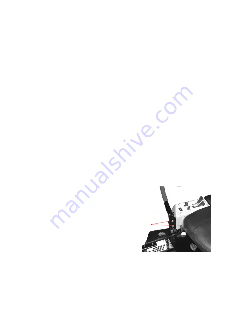
4.

To adjust the height of the lap bars,

a.

Remove the nuts from the lap bar mounting 
bolts (see Fig. 11).

b.

Remove the bolts and lap bar and repostion 
to the seconc set of holes in the mounting 
block.

c.

Replace the bolts and nuts and tighten to 
28-34 lb-ft.

1. If angular adjustments are also required, 

nuts can be tightened until snug at this 
point.

d.

The same adjustments should be made to 
both sides of the mower.

5.

To adjust the front-to-rear angle of the lap bars,

a.

Loosen the nuts on the lap bar mounting 
bolts, leaving the bottom one fairly snug.

b.

The top hole is slotted, allowing the lap bar 
to pivot on the bottom bolt.

c.

Move lap bar to the desired angle and 
tighten the nuts to 28-34 lb-ft.

Note:


In the neutral position, the handles of 

the lap bars should be aligned with approxi-
mately a one inch gap between the tips. Adjus-
the gap by adding shim washers to the top 
mounting bolt between the lap bar and the 
mounting block.

d.

Check the results of any adjustments to 
the conditions described in section a, 
above. Repeat any adjustment procedures 
as required until all conditions are met.

Figure. 11

Lap Bar Mounting 
Bolt and Nuts

Summary of Contents for 28HP Tank 53AB5JEZ630

Page 1: ...Hydrostatic Zero Turn Commercial Riding Mower Professional Turf Equipment OPERATOR S AND SERVICE MANUAL 60 72 Fabricated Deck InDirect Injection Diesel...

Page 2: ...des 16 F Cooling System 17 Maintenance and Service 17 A Mower Deck 17 B Hydraulic Oil 18 C Electrical System 19 D Tires 21 E Brakes 21 F Hydraulic System 22 G Cooling System 24 H Storage 24 Maintenanc...

Page 3: ...t upon the awareness concern prudence and proper training of the personnel involved in the oper ation transport maintenance and storage of the equipment WARNING The engine exhaust some of its constitu...

Page 4: ...ep all safety signs legible and properly installed 6 Do not check for hydraulic leaks with any part of the body 7 Do not add fuel to a machine when the engine is running and or the exhaust system is h...

Page 5: ...ded Loose connections at the battery terminals can produce sparks and heat connections to the terminals must be kept tight and the terminals and battery surfaces kept clean of acids and corro sion If...

Page 6: ...clothes lines guy wires buildings etc At other times and conditions ROPS and OPDs shall be in their fully upright and locked configurations DANGER Damaged ROPS and OPDs must be replaced prior to opera...

Page 7: ...y duty vinyl fabric it adjusts to recline up to 16 degrees and it will fold forward for transport or protection from the elements of weather lever actuated on operator s left side The armrests are adj...

Page 8: ...ne is running ROTATING BLADE DANGER Part Number 777S32798 Part Number 777S32797 Part Number 02003514 WARNING Maximum weight on hitch is 50 lbs Maximum towed load is 500 lbs Never allow passengers on t...

Page 9: ...erse Net Weight 1460 lbs w 60 deck 1540 lbs w 72 deck Operator Protective Device Roll Over Protective Structure and Retractable Seat Belts ENGINE INFO Engine 28 2HP InDirect Injection Caterpillar dies...

Page 10: ...hen turning downhill Control the speed and direction of the zero turn machine primarily with the speed directional control lap bar of the downhill side of the machine I E maintain the uphill side lap...

Page 11: ...n the opposite side of the area to be mowed post tree shrub etc b If on an hillside start at the bottom so that the turns are uphill rather than downhill c Align the mower so as to head directly towar...

Page 12: ...e on each drive wheel when the handle is pulled to the rear The brake must be engaged in order to start the engine 7 Foot Pedal Lift See Figure 3 Located on the right front corner of the mowing deck A...

Page 13: ...the tank stop DO NOT OVERFILL Space must be left for expansion see page 29 for more specs b Engine Oil Filled at the factory before shipment Pull out the oil dipstick wipe it off and reinsert it Pull...

Page 14: ...attained If the dimensions are not correct repeat steps c through f above 5 Lubricate all fittings listed in the mainte nance section D Zero Turn Break In And Operating Pro cedures DANGER Reread the...

Page 15: ...chine will turn toward the opposite from the side that was advanced I E to turn clockwise to the Right move the LEFT lap bar forward more than the right side and to turn counter clockwise to the LEFT...

Page 16: ...ays maintain a firm grip on the steering levers operate them smoothly and avoid any sudden movements of the levers when starting or stopping g To go forward move both steering levers slightly forward...

Page 17: ...ute Except for engine starting when the fan does not run for the first minute the fan blows downward to clear debris on the inlet screen for about 1 minute then upward for about 10 minutes this 1 and...

Page 18: ...y placing it on a blade balancer Do not use un balanced blades d If the blade dips on one end file stock off of the cutting surface on that end Note Blades that cannot be easily bal anced REPLACE 4 Ch...

Page 19: ...Replace and retighten nuts Figure 9 Hydraulic pumps Unfasten hose and drain from the bot tom of both pumps j Remove the three screws from the top of the oil filter and replace the oil filter element C...

Page 20: ...ing levers must be in the neutral position Once the engine is started the seat must be occupied and the parking brake must be released before either of the steering levers can be moved Also the seat m...

Page 21: ...t travel see tire side wall for proper inflation pres sure b Keep the valve caps tightened to prevent air pressure loss 2 Leaking Tires When a flat tire occurs repair or replace immediately The normal...

Page 22: ...rtain there are no kinks or twists in any hose 2 Hydraulic Oil Tank and Filter Note Change the hydraulic oil and the oil fil ter element after the first 50 hours of operation and every 500 hours there...

Page 23: ...s in their Neutral positions and to activate the Park Brake switch Both lap bars must be in their Neutral positions for the neutral lock linkage to func tion the spring loaded linkage will force rods...

Page 24: ...should be washed and cleaned b Sharpen the blades so that the mower will be ready to use when needed c Protect the metal surfaces Repair scratches with the appropriate touch up spray paint Brush a ru...

Page 25: ...s change the hydraulic oil and the hydraulic oil filter Change them every 500 hours thereafter Use Shell Rimula 15W40 or equivalent 6 Oil wear points Follow the Oiling Chart 7 Lubricate all grease fit...

Page 26: ...Pivots Transport Handle Pivots Transport Handle Pin Deck Frame Up and Down Pivots Seat Hinge Steering Lever Linkage Rod End Bearings Lever Return Assembly Rod End Bearings Pump Control Lever Pivots B...

Page 27: ...ngine up to operating temperature 3 Locate the Hour Meter Tachometer Service Minder display on the right hand operator con trol panel see Fig 1 on page 9 of the manual This display defaults to Tachome...

Page 28: ...ay in contact with the seat back 2 Lap bars should not contact operator s legs c In the full reverse position 1 Lap bars should not contact the opera tor s legs or torso 2 Set the seat to the preferre...

Page 29: ...ight blade when aligned along the mower centerline The blade to ground height at the rear of the blade tip should be 1 8 to 1 4 higher than the front tip This is referred to as blade pitch The sam hei...

Page 30: ...and 2 diesel fuel B5 are allowed Electrical shut off solenoid ESOS The ESOS is fit ted to the right hand side of the cylinder block at the rear of the fuel injection pump When the solenoid is de ener...

Page 31: ...31 WIRING DIAGRAM GD 02003026...

Page 32: ...32 Notes...

Page 33: ...33 Notes...

Page 34: ...34 Notes...

Page 35: ...35...

Page 36: ...o MTD Canada Ltd 2955 jean Baptiste Deschamps Ville Lachine Quebec H8T 1C5 or call 1 800 361 5770 or log on to our website at www cubcadet info This limited warranty does not provide coverage in the...

Reviews: