background image

Page 13

Fiberlink® 3X3X Series User’s Manual

Fiberlink® 3X3X Series

Certifications

Maintenance and Repairs

The Fiberlink® 3X3X Series has been manufactured using the latest semiconductor devices 
and techniques that electronic technology has to offer. They have been designed for long, 
reliable and trouble-free service and are not normally field repairable. 

Should difficulty be encountered, Communications Specialties maintains a complete 
service facility to render accurate, timely and reliable service of all products. 

The only maintenance that can be provided by the user is to ascertain that optical  
connectors are free of dust or dirt that could interfere with light transmission and that  
electrical connections are secure and accurate. Please see the Troubleshooting section of 
this manual for additional information.

An optical power meter, such as the Fiberlink® 6615, a visible light source, such as the  
Fiberlink® 6610, and a Three Wavelength Light Source, such as the Fiberlink® 6620, can 
greatly assist and expedite troubleshooting of fiber optic transmission systems and are 
recommended tools all installers should have available.

All other questions or comments should be directed to our Customer Service Department. 
It should be noted that many “problems” can easily be solved by a simple telephone call.

If you suspect your problem is caused by the optics or the fiber optic cable, and you have 
an optical power meter, please take the appropriate measurements prior to contacting 
support.

Maintenance and Repairs | Certifications

Summary of Contents for Fiberlink 3 Series

Page 1: ...Shaw Tower Singapore 189702 Tel 65 6391 8790 Fax 65 6396 0138 csiasia commspecial com commspecial com Communications Specialties Fiberlink 3X3X User s Manual The all digital Fiberlink 3X3X series all...

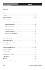
Page 2: ...ideo Specifications 4 Data Specifications 5 Optical Loss Budgets 5 Maximum Useable Distance 5 Installation Instructions 6 Alarm Switch Settings 7 Alarm Output Settings 7 Data Configuration Procedure 8...

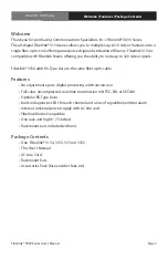
Page 3: ...ignals Fiberlink 3334 adds RS Type Data to the same fiber optic cable Features No adjustments pure digital processing and transmission Full color uncompressed real time transmission in NTSC PAL or SEC...

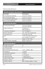
Page 4: ...e 0 to 55 degrees C Relative Humidity 10 90 non condensing Operating Power 95 250 VAC 47 63 Hz Size 1 75 H x 16 75 W x 10 D inches 44 H x 425 W x 254 D mm Weight Approx 5 5 lbs 2 5 kg Fiberlink Matrix...

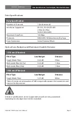
Page 5: ...s Budgets and Maximum Useable Distance Data Specifications Loss Budgets Maximum Distance 1310 nm S Version Fiber Type Loss Budget Distance Single Mode Fiber 0 20 dB 55km Multimode Fiber 62 5u 0 20 dB...

Page 6: ...iver units 5 When power is applied the green POWER LED should illuminate indicating the presence of operating power The Video LEDs will give an indication as described in the Indicator LED s and Alarm...

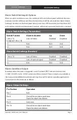
Page 7: ...larm Switch Settings Options When an alarm condition occurs the red Alarm LED on the front panel will blink the inter nal piezo sounder will beep and the external contacts will be activated see Alarm...

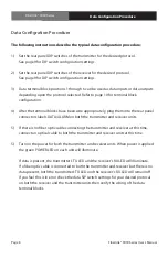
Page 8: ...the rear panel connectors labels DATA ALARM on both the transmitter and receiver units 5 If there is no fiber optic cable connecting the transmitter and receiver at this time connect an optical cable...

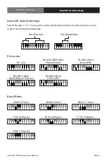
Page 9: ...5 6 7 8 9 10 11 12 2400 4 73ms 1 2 3 4 5 6 7 8 9 10 11 12 19 2k 620 sec 1 2 3 4 5 6 7 8 9 10 11 12 76 8k 150 sec 1 2 3 4 5 6 7 8 9 10 11 12 9600 1 10ms 1 2 3 4 5 6 7 8 9 10 11 12 57 6k 180 sec 1 2 3...

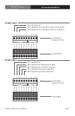
Page 10: ...7 8 9 10 DATA ALARM 1 2 3 4 5 6 7 8 9 10 DATA ALARM Terminal Block Receptacle on Unit Terminal Block Receptacle on Unit PIN 1 Signal Common PIN 2 Signal to be transmitted over fiber PIN 4 Signal being...

Page 11: ...k Receptacle on Unit Terminal Block Receptacle on Unit PIN 1 Shield Ground PIN 2 Signal to be transmitted received over from fiber PIN 3 Signal to be transmitted received over from fiber PIN 1 Shield...

Page 12: ...lure If these are off it usually means that the fiber is broken or has too much attenuation Next be certain that the input and output signal connections are correct An optical power meter such as the...

Page 13: ...light transmission and that electrical connections are secure and accurate Please see the Troubleshooting section of this manual for additional information An optical power meter such as the Fiberlink...

Page 14: ...cluding free materials and labor In no event shall CSI be responsible for any incidental or consequential damages or loss of profits or goodwill CSI shall not be obligated to replace or repair equipme...

Page 15: ...Power Meter measures the power of optical signals at 850 980 1310 and 1550 nm wavelengths allowing for convenient on site testing of fiber networks during construction and maintenance procedures It ca...

Page 16: ...Road 22 09 Shaw Tower Singapore 189702 Tel 65 6391 8790 Fax 65 6396 0138 csiasia commspecial com commspecial com 2010 Communications Specialties Inc All Rights Reserved Fiberlink and the starburst lo...

Reviews: