862-009
P2008 Jens Broecking © Firma WJG, Braunschweig. Nachdruck oder Vervielfältigung nur mit ausdrücklicher Genehmigung
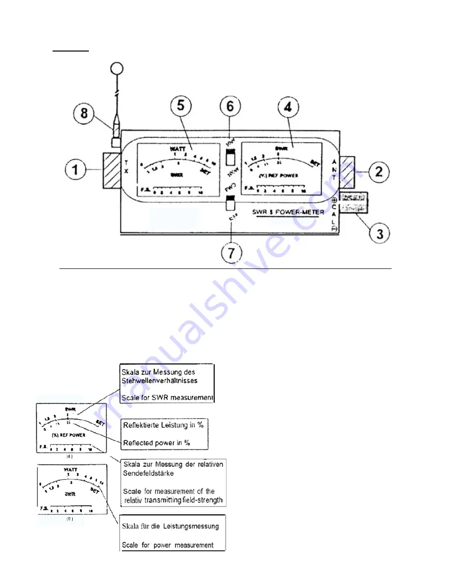
Functions:
1. TX: Connector for the radio installation.
2. ANT: Connector for the antenna installation.
3. CAL: Controller for calibrating the meter.
4. Analogue display of the SWR.
5. Analogue display of the transmitting power.
6. 10W/100W: Slide switch to set the testing range for the transmitting power.
7. FWD/REF: Slide switch of the sensors for the forward and the reflected electromagnetic wave.
8. Auxiliary antenna for measuring the field strength.
Displays:
In order that a radio transmitting device has a
maximal range it must transmit most of its power via
the antenna installation to the receiver. The
transmission of the radio waves between the radio
installation and the antenna installation should be
maximized while the reflection and absorption of the
same should be minimized.
The SWR shows the ration between maximal and
minimal value of a radio wave at the transition from
radio to antenna installation.
A disadvantageous SWR results from a mismatch of
impedance and wave resistivity of the antenna
installation.
You can try to minimize this mismatch but an
absolute adaptation is physical impossible.


