background image

Crystal Vision


Trouble shooting


Flip HD User Manual R1.1.doc 

15 

16/04/07


6 Trouble shooting 

Simple trouble shooting can be performed by using either the card edge or a remote status 
panel display.  

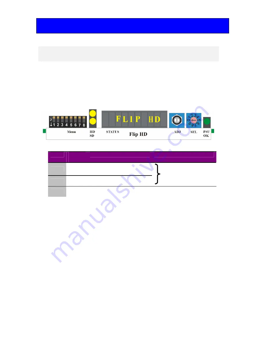
6.1  Card edge status LEDs 

Board edge LEDs provide status reporting and may be useful when fault finding. 


The following table summarises the card edge LED functions and colours: 

Name 

LED 

Colour 

Function when ON 

Function when Off 

HD 

Yellow 

Video input standard is HD 
(High Definition) 

SD 

Yellow 

Video input standard is SD 
(Standard Definition) 


Input not present 

PSU 

Green 

Good power supply (PSU) rails 

One or more of the monitor 
supplies is out of specification 


The board edge display may also give some useful information when trouble shooting  

Basic fault finding guide 


The Power OK LED is not illuminated 


Check that the frame PSU is functioning – refer to the appropriate frame manual for detailed 
information. 

There is no video output 


Check that a valid input is present and that any cabling is intact. Use the board edge, active control 
panel or Statesman status information to determine a likely fault.  

The video output exhibits jitter 


Check that the input signal stability is within normal limits and that the maximum cable length has not 
been exceeded. 

The card no longer responds to card edge or front panel control 


Check that the card is seated correctly and that the Power OK LED is lit. 

Check any active control panel cabling. 

Check if the control panel can control another card in the same rack. 

If necessary re-set the card by simply removing it from the rack whilst powered and re-inserting it 
after a few seconds. It is safe to re-insert the card whilst the rack is powered. 

Summary of Contents for Flip HD

Page 1: ...n Ltd Lion Technology Park Station Road East Whittlesford Cambridge CB22 4WL England E mail sales crystalvision tv Website www crystalvision tv Tel 44 0 1223 497049 Fax 44 0 1223 497059 Flip HD HD SD...

Page 2: ...2 Module configuration 5 3 Card edge operation 6 3 1 Card edge controls 6 3 2 Reading card edge LEDs 6 3 3 Card edge switch settings 7 Return to default values 7 Engineering menu 7 4 Using the front...

Page 3: ...1 Crystal Vision Flip HD User Manual R1 1 2 16 04 2007 Reset factory defaults 14 6 Trouble shooting 15 6 1 Card edge status LEDs 15 Basic fault finding guide 15 7 Specification 16 Revision 1 RM34 info...

Page 4: ...ked input and converted programme Flip HD block diagram The main features are as follows Reversed output image with bypass One frame video delay in all modes Two scaled outputs and two input loop thro...

Page 5: ...supply and will house up to two single height modules Note For details of fitting rear connectors please refer to the appropriate frame manual Rear module connections with RM34 The RM34 being a single...

Page 6: ...D modules per Indigo 4 frame 12 per Indigo 2 Six per Indigo 1 frame 2 per Indigo DT All frame slots can be used BNC I O assignment HD SD OUT Processed Serial Digital Output HD SD OUT Processed Serial...

Page 7: ...menus whilst the SEL rotary hex switch selects sub menus The ADJ shaft encoder is used to select an option within a menu or sub menu 3 2 Reading card edge LEDs Card edge LEDs may be used in conjuncti...

Page 8: ...on assigned 8 Down Not used No function assigned Return to default values Menu piano lever 3 DOWN all others in the UP position SEL No Menu Function and card edge display examples 0 Reset Rotate ADJ t...

Page 9: ...red prior to using the panel for the first time At power up the two line 20 character screen will display Crystal Vision followed by the firmware version number for the control panel All eight control...

Page 10: ...each menu HOME moves the display to the home menu ENTER accept current selection Upward arrow used to move up the menu structure enter lock panel menu from the Device menu Rotary control shaft encoder...

Page 11: ...main top level menus for the Flip HD module are obtained by pressing the F1 F4 keys from the HOME menu Menu keys are illuminated when active and when further menus are available The top level menus a...

Page 12: ...factory defaults This menu gives access to the reset control which will return all user controlled variables to their factory default values Reset menu Description From the Home menu press F2 to sele...

Page 13: ...Status The status menu contains various information about the board and the video input Flip HD status menu Description From the Home menu press F4 to select the status menu which is then traversed b...

Page 14: ...icates with each module in a frame through an active control panel An active panel must be fitted to allow for Statesman control 5 1 Statesman operation The initial view will show an Explorer style vi...

Page 15: ...The video standard is automatically detected and is shown The input format is indicated by the illumination of a green indicator Further status information is provided by the Statesman logging and ala...

Page 16: ...asic fault finding guide The Power OK LED is not illuminated Check that the frame PSU is functioning refer to the appropriate frame manual for detailed information There is no video output Check that...

Page 17: ...SD SDI 270Mb s to 1 485Gb s serial digital compliant to SMPTE 259M and SMPTE 292M HD Up to 140m with Belden 1694 or equivalent Belden 8281 or equivalent up to 100m SD 270Mb s 250 metres Outputs Numbe...

Reviews: