Appendix A
A-3
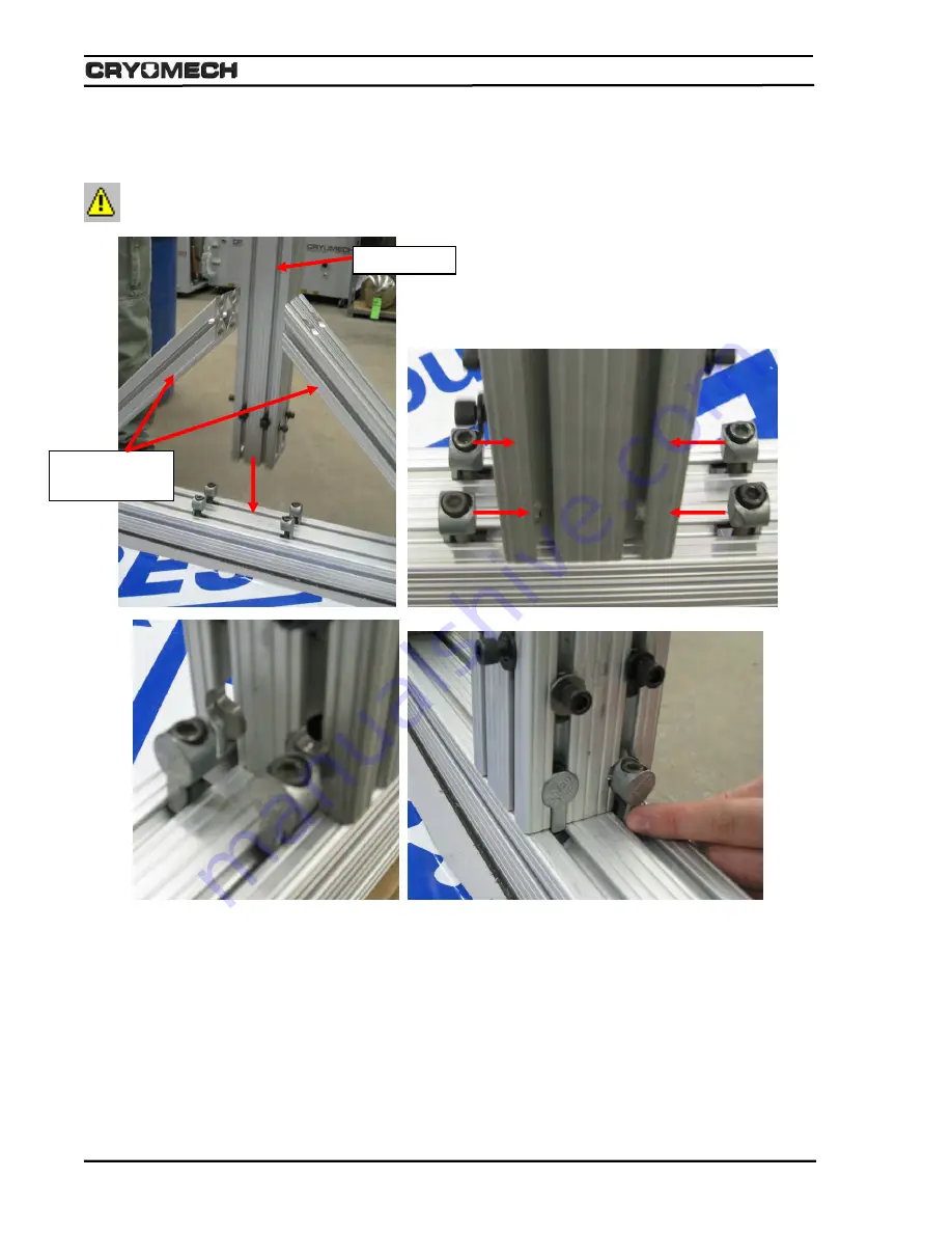
3) Place the main beam in between the two side supports and slide the main beam mounting hardware
into place. Be sure the winch faces the side of the base assembly with the single rear post mounted
to it. Do not fully tighten the hardware down.
Note: This is step takes two people to complete.
4) Slide the main beam side supports into place resting against the main beam making sure that the
main beam is centered onto the base assembly.
Main Beam
Main Beam
Side Supports
Summary of Contents for PT415
Page 1: ...PT415 Helium Reliquefier INSTALLATION OPERATION and ROUTINE MAINTENANCE MANUAL...
Page 4: ...1 1 Section 1 Overview...
Page 10: ...2 1 Section 2 Warranty...
Page 13: ...3 1 Section 3 Safety...
Page 20: ...4 1 Section 4 Inspection and Unpacking...
Page 24: ...5 2 Section 5 Specifications...
Page 39: ...Specifications 5 15 Figure 5 8 System I O wiring diagram Internal Supply Local Mode...
Page 40: ...Specifications 5 16 Figure 5 9 System I O wiring diagram Internal Supply Remote Mode...
Page 41: ...Specifications 5 17 Figure 5 10 System I O wiring diagram External Supply Local Mode...
Page 42: ...Specifications 5 18 Figure 5 11 System I O wiring diagram External Supply Remote Mode...
Page 45: ...6 2 Section 6 Installation...
Page 55: ...7 1 Section 7 Operation...
Page 68: ...8 1 Section 8 Routine Maintenance...
Page 77: ...Appendix A A 1 Figure A 1 Reliquefier Main Assembly Drawing...


