background image

Configuring the Trigger Outputs

You can configure the +12V trigger outputs in the OSD menu under MISC. The PINK wire (12V OUTPUT 

1) is Power Out 1 for the cameras and Power Out 2 is for the Smart-Play module. 

OSD Menu Menu Item Setting

Description

Option

Power Out 1 

(PINK)

CAN

+12V when the interface is on (red LED on)

ACC

+12V when ignition is on

Cam

+12V when camera input is activated               

(manually or automatically)

Power Out 2

CAN

Smart-Play power on.

OFF

Trigger output deactivated

Crux Interfacing Solutions • 21541 Nordhoff Street, Unit C, Chatsworth, CA  91311

phone: (818) 609-9299 • fax: (818) 996-8188 • www.cruxinterfacing.com

rev.072419

11 of 13

R

INTERFACING SOLUTIONS

ACPBM-77Y

Tip: We recommend for all camera to use power out setting “Cam” and for Smart-Play the power out 

setting of “CAN”.

Smart-Play Integration with Rear-View Camera Input for

E & F Series BMW Vehicles with CIC Infotainment Systems

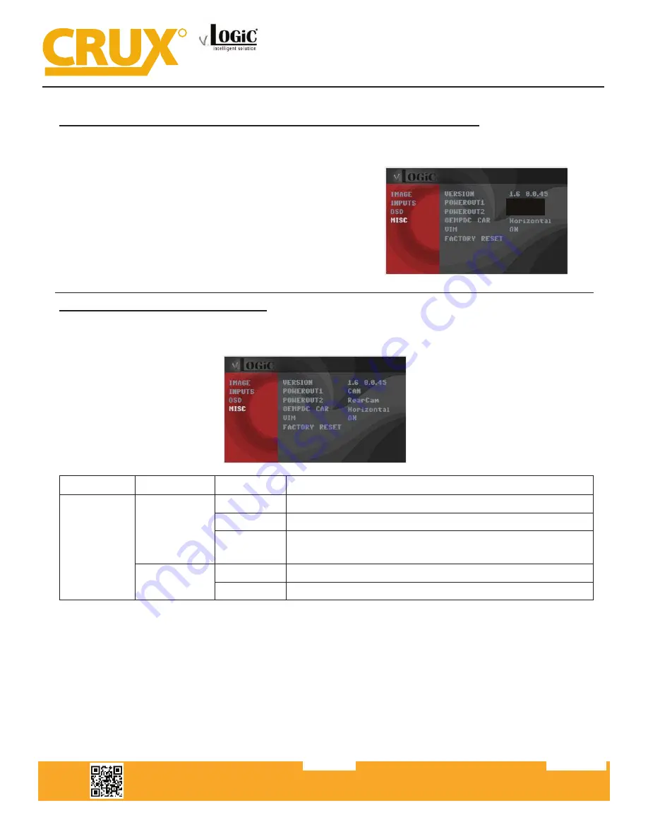
Power out settings for Rear Aftermarket Camera and Smart-Play

(Use the PINK (12V Output 1) wire to power the Rear camera)
In the OSD Menu under MISC, set “POWEROUT1” to 

CAM. And set “POWEROUT2” to CAN.

CAM

CAN

Summary of Contents for Logic ACPBM-77Y

Page 1: ...ol feature or the factory iDrive Knob Adds aftermarket rear view camera input Picture in picture mode combining after market rear view picture with factory parking sensor graphics Built in on screen display and setup 1 trigger output 12V max 1A for the camera power NOTE Android Phones must have a firmware version of 8 and above PRODUCT FEATURES PARTS INCLUDED ACPBM 77Y Module Power CAN Harness 1 E...

Page 2: ...r on Smart Play Harness Power CAN Harness iDrive Knob Retention Cable ACPBM 77Y Module ACC Power Ground Constant LVDS IN LVDS OUT v 1 2 3 O N Intelligent Solution LVDS OUT LVDS IN Crux Interfacing Solutions 21541 Nordhoff St Unit C Chatsworth CA 91311 rev 040119 2 of 12 INSTALLATION DIAGRAM R INTERFACING SOLUTIONS DIP SWITCH SETTINGS VEHICLE SCREEN SIZE DIP 1 DIP 2 DIP 3 CIC E E Series 6 5 OFF OFF...

Page 3: ...ully remove the hazard door unlock panel and unplug the harness 4 Remove the push to start panel and its connector to fully take off the front panel 5 Remove the A C control panel using a trim removal tool along with the cables connected to it 6 Carefully remove the Headunit panel 7 Remove the 4 screws bracing the Headunit 8 Remove the Headunit to gain access to its backside 9 Unplug the Quadlock ...

Page 4: ...wer Video harness to the green 12V output on the ACPBM 77Y harness 13 Tap the Yellow constant wire from the Smart Play Power Video harness to the Red constant wire on the ACPBM 77Y vehicle harness Male Side 14 Connect the male 8 pin connector from the ACPBM 77Y to the female 8 pin connector on the Power CAN harness Make sure you use the correct Power CAN har ness for your vehicle trim refer to NOT...

Page 5: ...stalling on an E series trim Power CAN 1 you can skip steps 23 28 Refer to P 7 for the wiring diagram for the F series if needed 23 Carefully remove the center trim using a trim removal tool to get under neath the iDrive knob 24 Your vehicle may have a 4 pin or 10 pin connector for the iDrive knob Remove the iDrive connector 25 Using a pin removal tool remove the Green CAN LO Pin 4 and Orange Gree...

Page 6: ...ge is displayed in step 26 If retaining an OEM camera or if you re not installing a back up camera skip steps 25 and 26 32 Tap the camera power wire to the PINK power output 1 wire 33 Connect the audio out RCAs from the Power Video harness to the RCA inputs on the 3 5mm to RCA adapter 34 Plug in the 3 5mm jack into the vehicle s factory AUX input 35 Mount the microphone to a loca tion of your choi...

Page 7: ...1 Check the OSD settings and make sure they match those on the next page Test the Back Up camera Put gear in reverse and check for rear camera image on screen Go to Smart Play mode and test for functionality Once the cameras and Smart Play validation is complete mount the ACPBM 77Y and Smart Play modules And finally reinstall all the components to their original set up 40 Test the communication Tu...

Page 8: ...W version Factory Reset CONNECTING THE SMART PLAY INTERFACE plugged in to the USB port using the smartphone s OEM charger data cable The USB port on the ACPBM 77Y can be used to charge the Apple device or play videos or music from a USB thumb drive to the next enabled input If all inputs are enabled the order is Rear CAM Video Input Smart Play Repeat The ACPBM 77Y u lizes wireless technology for A...

Page 9: ...ove will appears on the screen the BT device name and pairing code 0000 device and connect to CRUX Smart Play_XXXX 4 Once the ACPBM 77Y has connected via Bluetooth it 5 Use the iDrive knob to navigate the cursor to the 6 Image above shows the Home Screen once the smartphone is connected Smart Play Integration with Rear View Camera Input for E F Series BMW Vehicles with CIC Infotainment Systems NOT...

Page 10: ... vated OFF Video In Mo on deac vated NOTE The Video In Mo on func on is permanently ac ve without disturbing the naviga on performance Selecting theInterface as Current AV Source Smart Play Integration with Rear View Camera Input for E F Series BMW Vehicles with CIC Infotainment Systems Display settings for Smart Play Adjust brightness contrast and saturation for a more defined image To get to the...

Page 11: ...n OFF Trigger output deactivated Crux Interfacing Solutions 21541 Nordhoff Street Unit C Chatsworth CA 91311 phone 818 609 9299 fax 818 996 8188 www cruxinterfacing com rev 072419 11 of 13 R INTERFACING SOLUTIONS ACPBM 77Y Tip We recommend for all camera to use power out setting Cam and for Smart Play the power out setting of CAN Smart Play Integration with Rear View Camera Input for E F Series BM...

Page 12: ...of 13 R INTERFACING SOLUTIONS ACPBM 77Y OSD Settings You can change the basic configurations of the interface in the OSD on screen display OSD Menu Menu Item Setting Description OSD POS X 0 xxx Horizontal position of the OSD POS Y 0 xxx Vertical position of the OSD Size Small Small OSD menu window Large Large OSD menu windows Osd TimeOut 2 20 Time setting for automatic OSD shutoff Info Version X X...

Page 13: ...ERIES 2005 2011 3 Series Sedan 2005 2011 3 Series Wagon 2006 2013 3 Series Coupe 2007 Up 2005 2011 3 Series Sedan 2005 2011 3 Series Wagon 2006 2013 3 Series Coupe 2007 Up 5 SERIES 2011 Up 5 Series 2012 Up 5 Series Sports Wagon Each short press will switch to the next enabled input If all inputs are enabled the order is FRONT CAM REAR CAM 6 Series 2011 Up 6 Series 7 Series 2008 Up 7 Series 2009 Up...

Reviews: