Section 4
4-12
460 Express Series
PMES
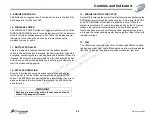
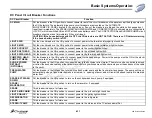
This circuit breaker connects power to solenoids PME-1 and PME-2 which feed power to the two control circuit PMEs
(Power Management Enclosures) in the Grayhill control system, PME-1 and PME-2 have outputs that are controlled by
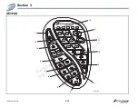
the keypad mounted at the helm.
SHOWER SUMPS
This breaker connects power to the shower sump pumps for automatic pump operation. The shower sump pumps are
turned on by float switches when the water level causes the float switches to rise. In addition to the showers, air condition-
ers and sinks drain into the sumps, requiring continuous automatic operation.
C.O. DETECTORS
This breaker connects power to the CO detectors. The breaker is connected to the +12 volts house battery switch, bypass-
ing the DC MAIN circuit breaker for continuous CO detection. Reset this breaker immediately if it is tripped.
BLOWERS ON
This switch controls the engine room blowers. Switch the blowers on for at least four minutes prior to starting the engines
or generator to rid the engine room of fumes.
GENERATOR
Push the START switch until you hear that the generator has started, then release the switch. To stop push the STOP
switch and hold it in until the generator stops.
AUXILIARY ENGINE
CONTROL
These switches are used to start and stop the engines in the event that the keypad is not used for these functions. In
normal operation the keys should be removed and the engine start/stop functions controlled from the keypad.
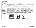
ADDITIONAL
CIRCUIT BREAKER
PANELS
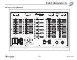
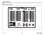
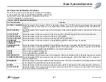
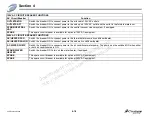
There are three additional circuit breaker panels located in the yacht for localized functions. The panel locations and func-
tions are shown.
DC Circuit Breaker
Function
35-E001B-Manual
LOCATED ON THE FORWARD BULKHEAD IN THE ENGINE ROOM
PANEL LOCATED BELOW THE DASH
LOCATED ADJACENT TO AC/DC PANEL
Downloaded
from
CruisersOwnersForum
http://www.CruisersOwnersForum.com


