2
Rhino Jr RJ400 Quick Start Guide
3
Rhino Jr RJ400 Quick Start Guide
PMS 711
2 cyan
85 magenta
76 yellow
10.25.12
CRU Mark
1 HARDWARE SETUP
1.1 FRAME INSTALLATION
a. Slide the Rhino Jr RJ400 removable drive enclosure into three open 5.25” drive bays in
your computer workstation.
b. Secure the RJ400 to the chassis with the mounting screws provided.
c. Attach four SATA data cables to the SATA connectors on the rear of the RJ400 (HD1, HD2,
HD3, and HD4) and attach the other end to the appropriate SATA ports on the computer’s
motherboard or SAS/SATA host card.
d. Attach two SATA power connectors from your workstation’s power supply to the two SATA
power connections on the rear of the RJ400 (POWER1 and POWER2). If your workstation
lacks SATA power connectors, you can use two Molex 4-pin power connectors instead.
1.2 DRIVE INSTALLATION
a. Eject the carrier from the frame by pressing in on the triangle symbol on the carrier.
b. Carefully insert a hard drive into the carrier and turn the drive/carrier assembly over.
c. Bottom-mount the drive into the carrier with the mounting screws provided.
d. With the carrier handle still ejected from the carrier, slide the drive ports-first into the drive
bay and apply firm pressure until the drive is seated.
e. Push the carrier handle in so it’s flush with the carrier.
f. You can optionally rotate the lock switch on the carrier 90 degrees clockwise to secure the
carrier into the RJ400.
g. Press the carrier’s power button to the right of the carrier to power on the drive.
2 EJECTING DRIVES FROM THE RJ400
After ejecting a drive, you may need to restart your computer in order to remount the
drive unless you have a hotswap-capable host.
2.1 WINDOWS
a. Ensure that no file transfers are taking place by making sure that the Drive Power Switch
LED for that drive is not blinking, as disconnecting the unit while a file transfer is in prog-
ress can result in data loss.
b. Then press the power switch to turn off the drive in the carrier.
c. If the lock is engaged, rotate the lock switch 90 degrees counterclockwise.
d. Eject the carrier from the frame by pressing in on the triangle symbol on the carrier.
If you have a SAS/SATA host card or motherboard that supports hot-swapping,
then you should first unmount the volume by left-clicking on the the USB plug icon
with the green checkmark on the Desktop task bar and then selecting the proper
device from the menu that pops up. Volumes not on a hotswap-capable host may
not appear here.
2.2 OS X/macOS
a. First, ensure that no file transfers are taking place by making sure that the Drive Power
Switch LED for that drive is not blinking, as disconnecting the unit while a file transfer is in
progress can result in data loss.
b. Unmount the volume before powering down the drive by dragging the volume’s icon to the
Trash
, or by selecting the volume and pressing
C E
.
c. Press the power switch to turn off the drive in the carrier.
d. If the lock is engaged, rotate the lock switch 90 degrees counterclockwise.
e. Eject the carrier from the frame by pressing in on the triangle symbol on the carrier.
3 LED BEHAVIOR
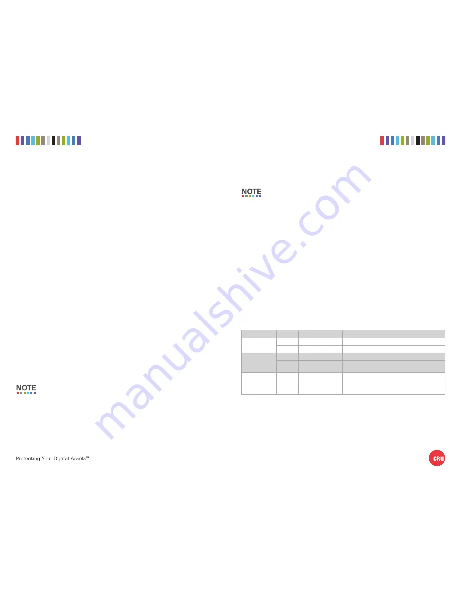
LED NAME
COLOR
STATE
DESCRIPTION
Drive Power
Switch
Green
Solid
The drive is powered on.
Amber
Blinking or Solid
The drive is being accessed by the computer host.
Fan
Green
Solid
The fan is operating properly.
Red
Solid
The fan has failed. Please contact CRU Technical Sup-
port.
OverTemp/Reset
Red
Blinking
The internal unit temperature has reached the preset
threshold (see Section 4 for info on how to set the
threshold). The default threshold is 140° F/60° C. Press
the
Reset button
to silence the alarm.
4 TEMPERATURE ALARM THRESHOLD
The default temperature alarm threshold can be changed by moving jumper JP1 on the rear of the
RJ400 enclosure. The default threshold is 140° F/60° C. You can move the jumper to 131° F/55° C
or to 149° F/65° C.


