background image

Page 27

Com-Tech 200/400/800/1600  Power Amplifiers

FAULT

ONLY ONE CHANNEL SHOWN

NPN HI

OUTPUT

STAGE

NPN L

O

W

OUTPUT

STAGE

PNP L

O

W

OUTPUT

STAGE

PNP HI

OUTPUT

STAGE

+

OUTPUT

+Vcc

Vcc

TRANSLATOR

LV

A

LV

A

+Vcc

Vcc

BIAS

CURRENT

LIMIT

TRANSLATOR

BALANCE

INPUT STAGE

P.I.P.

BALANCED

INPUT

VARIABLE

GAIN STAGE

ERROR

AMP

DISPLAY

BIAS

BRIDGE

BALANCE

+Vcc

Vcc

POWER

SUPPLY

CONTROL

DC

/L

F

TIMER

POWER

+Vcc

Vcc

ODEP

A

B

A

(ODEP)

B

(ODEP)

SUPPL

Y

D

E

(DISPLAY)

D

C

(DISPLAY)

E

HS

TEMP

C

(ODEP)

+24

24

ENABLE

BARRIER

BLOCK

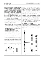
Fig. 5.1  Circuit Block Diagram

Summary of Contents for Com-Tech 1600

Page 1: ... by Crown International Inc P O Box 1000 Elkhart Indiana 46515 1000 U S A Telephone 219 294 8000 Com Tech amplifiers are produced by the Professional Audio Division of Crown International Inc Trademark Notice SmartAmp MPX 6 SMX 6 AMB 5 and Grounded bridge are trademarks and Amcron Crown Techron Com Tech IOC ODEP IQ System P I P and TEF are registered trademarks of Crown International Inc Other tra...

Page 2: ...t Mishawaka Road Elkhart Indiana 46517 4095 U S A warrants to you the ORIGINAL PURCHASER and ANY SUBSEQUENT OWNER of each NEW Crown product for a period of three 3 years from the date of purchase by the original purchaser the warrantyperiod thatthenewCrownproductisfreeofdefects in materials and workmanship and we further warrant the new Crown product regardless of the reason for failure except as ...

Page 3: ...cating the amplifier s in the bottom of the rack and the pream plifier or other sensitive equipment at the top Printed on recycled paper The lightning bolt triangle is used to alert the user to the risk of electric shock WATCH FOR THESE SYMBOLS The exclamation point triangle is used to alert the user to important operating or maintenance instructions The information furnished in this manual does n...

Page 4: ...4 3 Protection Systems 23 4 3 1 ODEP 23 4 3 2 Standby Mode 24 4 3 3 Transformer Thermal Protection 24 4 3 4 Circuit Breaker 24 4 4 Controls 25 4 5 Filter Cleaning 25 5 Technical Information 26 5 1 Overview 26 5 2 Circuit Theory 26 5 2 1 Dual Operation 26 5 2 2 Bridge Mono Operation 28 5 2 3 Parallel Mono Operation 28 6 Specifications 29 7 AC Power Draw and Thermal Dissipation 42 8 Accessories 44 8...

Page 5: ...ates 23 4 2 Input Sensitivity Switch 25 5 1 Circuit Block Diagram 27 6 1 Com Tech 200 Minimum Power Matrix 32 6 2 Com Tech 400 Minimum Power Matrix 33 6 3 Com Tech 800 Minimum Power Matrix 34 6 4 Com Tech 1600 Minimum Power Matrix 35 6 5 Com Tech 200 Maximum Power Matrix 36 6 6 Com Tech 400 Maximum Power Matrix 37 6 7 Com Tech 800 Maximum Power Matrix 38 6 8 Com Tech 1600 Maximum Power Matrix 39 6...

Page 6: ...0 1600 Power Amplifiers Fig 1 1 Com Tech Amplifiers 120 VAC 60 Hz Units POW ER ODEP IOC SPI ENABLE CH1 CH2 OFF POW ER ODEP IOC SPI ENABLE CH1 CH2 OFF POW ER ODEP IOC SPI ENABLE CH1 CH2 OFF POW ER ODEP IOC SPI ENABLE CH1 CH2 OFF ...

Page 7: ...e P I P Programmable Input Processor connector accepts accessories that tailor the amplifier to suit specific applications Drives constant voltage lines without lossy distortion producing step up transformers Two mono modes Bridge Mono and Parallel Mono for driving a wide range of load impedances Very low harmonic and intermodulation distortion give the best dynamic transfer function in the indust...

Page 8: ...ut put waveform differs from the input by 0 05 or more see Section 4 2 Note The channel 2 IOC indicator will stay on in Parallel Mono mode E Signal Presence Indicators SPI The signal presence indicators flash synchronously with the amplifier s audio output see Section 4 2 F Enable Indicator This indicator lights when the amplifier has been en abled or turned on and AC power is available see Sectio...

Page 9: ... channel independently for either 8 4 ohm loads or 70 volt constant voltage lines WARNING Do not change these switches unless the amplifier is off Do not attempt to use the Bridge Mono or Parallel Mono modes unless these switches are set the same Also be sure to follow the special installation requirements for each mode see Section 3 3 1 O Output Barrier Block A barrier block with four terminals i...

Page 10: ...ight A 3 5 inches 8 9 cm Models Com Tech 200 All Com Tech 400 North American Height B 5 25 inches 13 3 cm Models Com Tech 400 100 120 VAC 50 60 Hz Com Tech 400 220 240 VAC 50 60 Hz Com Tech 800 All Height C 7 inches 17 8 cm Model Com Tech 1600 All 3 2 Cooling It is important to understand cooling considerations when installing a Com Tech amplifier First never block the amplifier s front or side ai...

Page 11: ...ont door it is usually best to leave it open and avoid blocking the air intakes If this is impossible supple ment the air flow by mounting a grille in the door or with a rack mounted blower If you install a grille in the door we recommend wire grilles over perforated panels be cause wire tends to cause less air restriction perfo rated panels cause a minimum air restriction of 40 A better choice fo...

Page 12: ... panel If Bridge Mono mode is used with 70 volt output the amplifier will actually deliver 140 volts more informa tion is provided later in this section To effectively use this mode you may need to cross reference power rat ings for the step down transformer taps using Crown s constant voltage computer see Section 8 3 BLOWER OPTION 2 BLOWER OPTION 1 AIR FLOW FRONT OF RACK DOOR AIR FLOW EQUIPMENT R...

Page 13: ...be set the same 8 4 ohm or 70 volt mode when operating in Bridge Mono or Parallel Mono mode When connecting a 70 volt step down transformer do not exceed its power rating Too much power can saturate a transformer and cause it to appear as a short circuit to the amplifier If this happens no dam age should occur but the amplifier may run less effi ciently 70 VOLT 8 4 OHM 8 4 O H M 8 4 ohm mode is co...

Page 14: ...e amplifier into Dual mode turn it off slide the dual mono switch to the center position and properly connect the output wiring Be sure to observe correct loudspeaker polarity see Figure 3 4 and be careful not to short the two outputs CAUTION Never tie an amplifier s outputs together di rectly and never parallel them with the output of an other amplifier Such connections do not result in increased...

Page 15: ... Only connect balanced equipment meters switches etc to the Bridge Mono output Both sides of the line must be isolated from the input grounds or os cillations may occur BRIDGE MONO DUAL PARALLEL MONO P A R A L L E L M O N O Parallel Mono mode is used to drive loads with a total impedance of less than 4 ohms when using 8 4 ohm output mode see Bridge Mono if the load is greater than 4 ohms This mode...

Page 16: ...M MODE TURN OFF THE AMPLIFIER BEFORE CHANGING THE DUAL MONO SWITCH NOT USED BRIDGE MONO DUAL PARALLEL MONO BB Programmable Input Processor P I P C H 2 I N P U T C H 1 I N P U T 70 VOLT 70 VOLT 8 4 OHM 8 4 OHM CH1 CH2 TURN OFF THE AMPLIFIER BEFORE CHANGING THE OUTPUT MODE SWITCHES WARNING BOTH CHAN NELS MUST BE SET TO 8 4 OHM MODE CH 2 CH 1 0 dB 5 1 2 3 4 5 6 7 8 9 10 11 13 15 17 19 21 25 32 0 dB 5...

Page 17: ...by overload ing or overheating them To attenuate such frequen cies place a capacitor in series with the input signal line The graph in Figure 3 10 shows some capacitor values and how they affect frequency response Use only low leakage capacitors Another problem to avoid is large levels of radio fre quencies or RF in the input signal Although high RF levels may not pose a threat to the amplifier th...

Page 18: ...bles parallel to power cables or near power transformers A ground loop can occur when the mag netic field generated by the 50 60 Hz alternating cur rent in the power cable or transformer is induced into the input cables To prevent this you can lace the in put cables along their length Lacing cables helps re duce magnetically induced current by minimizing the cross sectional area between conductors...

Page 19: ...mograph 2 Select an acceptable damping factor and mark it on the Damping Factor line Your amplifier can provide an excellent damping factor of 1 000 from 10 to 400 Hz in Stereo mode with an 8 ohm load In contrast typical damping factors are 50 or lower Higher damping factors yield lower distortion and greater motion control over the loudspeakers A common damping factor for commercial applications ...

Page 20: ...sub sonic currents when primarily inductive loads are used Examples of inductive loads are 70 volt trans formers and electrostatic loudspeakers Inductive loads can appear as a short circuit at low fre quencies This can cause the amplifier to produce large low frequency currents and activate its protec tion circuitry Always take the precaution of installing a high pass filter in series with the amp...

Page 21: ...s are protected by slow blow fuses and high frequency drivers are pro tected by high speed instrument fuses Depending on the application you may want to use a P I P module to protect your loudspeakers When properly configured all P I P modules with signal driven compression can provide loudspeaker protec tion Some of the P I P modules with signal driven compression include the P I P AMCb P I P EDC...

Page 22: ... has been turned on or en abled and that its low voltage power supply is working It does not indicate the status of the high volt age power supplies For example the Enable indicator will remain lit in the unlikely event that one of the amplifier s protection systems described in Sec tion 4 3 removes power from one or both high volt age supplies to put the channel in standby mode The Enable indicat...

Page 23: ...mplifier channel is in standby mode Possible reasons 1 The DC low frequency protection circuitry has been activated 2 The fault protection circuitry has been activated after sensing heavy common mode current 3 The transformer thermal protection circuitry has been activated ODEP limiting has been activated Possible reasons 1 The amplifier s air filters are blocked and need to be cleaned 2 There is ...

Page 24: ...avy common mode current unless its circuitry is damaged in some way and putting the channel in standby mode helps to prevent further damage The amplifier s transformer thermal protection circuitry is activated in very unusual circumstances where the unit s transformer temperature rises to unsafe levels Under these abnormal conditions the amplifier will put both channels into standby mode In additi...

Page 25: ...or 70 volt mode If desired the sensitivity can be switched to a voltage gain of 26 dB With 26 dB gain and 70 volt output the input sensitivity for all models is 3 5 volts With 26 dB gain and 8 4 ohm output the in put sensitivity varies among the different amplifier 0 77 V sensitivity 8 4 ohm 26 dB gain SENSITIVITY SWITCH INSIDE ACCESS HOLE 0 77 V sensitivity 70 volt THIS AMPLIFIER IS EQUIPPED WITH...

Page 26: ...NP stage while synchronously decreasing conductance of the high side PNP and low side NPN The two channels may be used together to double the voltage Bridge Mono or current Parallel Mono pre sented to the load This feature gives you flexibility to maximize power available to the load A wide bandwidth multiloop design is used for state of the art compensation This produces ideal behavior and result...

Page 27: ...TAGE OUTPUT Vcc Vcc TRANSLATOR LVA LVA Vcc Vcc BIAS CURRENT LIMIT TRANSLATOR BALANCE INPUT STAGE P I P BALANCED INPUT VARIABLE GAIN STAGE ERROR AMP DISPLAY BIAS BRIDGE BALANCE Vcc Vcc POWER SUPPLY CONTROL DC LF TIMER POWER Vcc Vcc ODEP A B A ODEP B ODEP SUPPLY D E DISPLAY D C DISPLAY E HS TEMP C ODEP 24 24 ENABLE BARRIER BLOCK Fig 5 1 Circuit Block Diagram ...
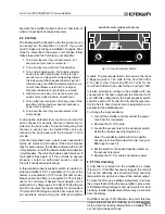
Page 28: ...or stage previously mentioned removing any further drive that may exceed the safe operating area of the output stage Thermal sensors S100 and S200 give the ODEP cir cuits vital information on the operating temperature of the heat sink on which the output devices are mounted Should the amplifier fail in a way that would cause DC across the output lead the DC protection circuit senses this on the ne...

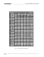
Page 29: ...5 at full bandwidth power from 20 Hz to 1 kHz increasing linearly to less than 0 1 at 20 kHz Intermodulation Distortion IMD 60 Hz and 7 kHz 4 1 Less than 0 05 from less than 166 milliwatts to full bandwidth power Damping Factor Greater than 1000 from 10 Hz to 400 Hz see Figure 6 10 Crosstalk See Figure 6 13 Common Mode Rejection Ratio CMRR Better than 70 dB Slew Rate Greater than 17 volts per micr...

Page 30: ... to each channel Input Impedance Nominally 20 K ohms balanced Nominally 10 K ohms unbalanced Input Sensitivity Settings include 0 775 volts for 8 4 ohm output 0 775 volts for 70 volt output and a volt age gain of 26 dB Output Connector A back panel barrier block with two Parallel Mono mode 440 watts into 2 ohms 440 watts into 4 ohms 455 watts with 70 volt output Com Tech 800 Dual mode with both ch...

Page 31: ... amperes Com Tech 1600 30 amperes All 220 240 VAC Units Com Tech 200 4 amperes Com Tech 400 8 amperes Com Tech 800 10 amperes Com Tech 1600 20 amperes Construction Durable black finish on the steel chassis front panel Lexan overlay and specially designed flow through ventilation from front to side panels Cooling Internal heat sinks with on demand forced air cooling fan is optional for the North Am...

Page 32: ...ono 125 105 95 250 205 190 135 110 100 275 215 205 270 210 205 145 110 105 290 220 205 290 215 210 135 105 95 265 210 195 At 0 05 THD See note 3 1 kHz 145 105 110 295 215 205 290 210 205 145 110 105 285 220 205 285 210 205 100 120 VAC 50 60 Hz Dual both channels driven Bridge Mono balanced output Parallel Mono 130 105 95 260 215 195 140 110 105 280 225 210 275 220 210 150 115 105 300 230 215 300 2...

Page 33: ...0Hz 20kHz 215 210 215 425 425 435 Dual both channels driven Bridge Mono balanced output Parallel Mono 200 200 210 380 405 415 225 215 220 430 430 440 420 435 440 240 220 225 465 435 455 450 445 455 215 205 220 415 410 435 At 0 05 THD See note 3 1 kHz 235 220 225 465 440 450 430 440 450 235 215 225 455 435 450 445 445 450 100 120 VAC 50 60 Hz Dual both channels driven Bridge Mono balanced output Pa...

Page 34: ... 20kHz 460 295 455 935 600 905 Dual both channels driven Bridge Mono balanced output Parallel Mono 425 290 400 840 575 800 445 295 410 890 595 830 895 595 830 460 300 425 925 600 855 925 600 855 440 290 415 885 580 825 At 0 05 THD See note 3 1 kHz 480 300 455 965 605 905 950 600 905 460 295 420 915 595 850 920 595 845 100 120 VAC 50 60 Hz Dual both channels driven Bridge Mono balanced output Paral...

Page 35: ...10 1 595 1 040 1 725 Dual both channels driven Bridge Mono balanced output Parallel Mono 510 1 020 530 815 1 055 1 625 1 060 1 620 815 535 860 1 625 1 070 1 700 1 660 1 080 1 700 775 515 830 1 545 1 035 1 640 At 0 05 THD See note 3 1 kHz 860 535 955 1 725 1 070 1 795 1 720 1 070 1 760 805 530 850 1 615 1 060 1 695 1 640 1 070 1 690 100 120 VAC 50 60 Hz Dual both channels driven Bridge Mono balance...

Page 36: ...o the ampli fier and monitored for nonlinear distortion The average power during the burst is reported Loud speakers must be able to withstand this level if they are to be safely used with this amplifier 2 A 40 millisecond sine wave burst 10 percent duty cycle is presented to the amplifier and monitored for nonlinear distortion Aver age power during the burst is reported This power level is a meas...

Page 37: ...5 1 110 665 645 1 080 655 645 Com Tech 400 Maximum Power Watts Dual Mono Mode 40 Millisecond Tone Burst At 0 05 THD See note 2 Single Cycle Tone Burst At less than 0 05 THD See note 1 50 Hz 1 kHz Load in Ohms Constant Voltage 20 Hz 50 Hz 1 kHz 450 355 330 855 705 655 810 700 655 550 325 315 1 095 660 630 1 070 640 620 7 kHz 7 kHz AC Mains 120 VAC 60 Hz 100 120 VAC 50 60 Hz Dual both channels drive...

Page 38: ...00 810 1 230 1 485 805 1 210 Com Tech 800 Maximum Power Watts Dual Mono Mode 40 Millisecond Tone Burst At 0 05 THD See note 2 Single Cycle Tone Burst At less than 0 05 THD See note 1 50 Hz 1 kHz Load in Ohms Constant Voltage 20 Hz 50 Hz 1 kHz 690 375 575 1 385 755 1 145 1 380 755 1 135 730 370 595 1 480 790 1 190 1 450 780 1 185 7 kHz 7 kHz AC Mains 120 VAC 60 Hz 100 120 VAC 50 60 Hz Dual both cha...

Page 39: ...50 1 295 2 700 1 475 2 550 2 715 1 470 2 530 Com Tech 1600 Maximum Power Watts Dual Mono Mode 40 Millisecond Tone Burst At 0 05 THD See note 2 Single Cycle Tone Burst At less than 0 05 THD See note 1 50 Hz 1 kHz Load in Ohms Constant Voltage 20 Hz 50 Hz 1 kHz 1 215 655 1 170 2 420 1 285 2 225 2 390 1 300 2 280 1 335 720 1 255 2 680 1 440 2 490 2 630 1 425 2 430 7 kHz 7 kHz AC Mains 120 VAC 60 Hz 1...

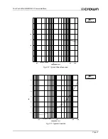
Page 40: ... 0 1 2 3 4 dB 5 6 7 4 ohm 8 ohm 1 watt 504 0 126 8 31 8 MILLIOHMS 8 0 2 0 6 dB 20 100 1 K 10 K 20 K 400 200 100 0 600 800 1000 1200 1400 FREQUENCY Hz 8 ohm 10 100 1 K 10 K 100 K FREQUENCY Hz Fig 6 9 Typical Frequency Response Fig 6 10 Typical Damping Factor Fig 6 11 Typical Output Impedance ...

Page 41: ...1600 Power Amplifiers TECHRON TEF 45 0 45 100 1 K 10 K 20 K FREQUENCY Hz 100 1 K 10 K 20 K FREQUENCY Hz dB TECHRON TEF 66 72 78 84 90 96 102 Fig 6 12 Typical Phase Response Fig 6 13 Typical Crosstalk TEF Measurement TEF Measurement ...

Page 42: ...iescent power draw includes both the amplifier s quiescent power draw for the se lected output mode and the power drawn by the fan if one is installed these values are listed in the previous column The following equation converts power draw in watts to current draw in amperes Current Draw amperes AC Mains Power Draw watts x AC Mains Voltage Power Factor 83 The power factor of 0 83 is needed to com...

Page 43: ... 370 220 285 240 195 150 100 810 670 525 385 245 1190 1020 850 680 510 6 4 5 3 4 2 3 0 1 9 9 9 8 0 6 2 4 4 2 6 9 7 8 0 6 3 4 6 2 9 Duty Cycle AC Mains Power Draw Watts btu hr Current Draw Amps 2 9 2 4 1 9 1 4 0 9 4 5 3 7 2 8 2 0 1 2 4 4 3 6 2 9 2 1 1 3 4 Ohm Dual 8 Ohm Bridge Mono 2 Ohm Parallel Mono 70 V Com Tech 800 200 170 140 115 85 kcal hr 1125 945 765 585 405 300 260 215 170 130 100 120 V 22...

Page 44: ...trol interrupt driven report ing that lets you define error conditions and configur able short detection CLP Programmable Input Processor P I P 3 1 2 GND INPUT INPUT CH 2 CH 1 PUSH PUSH P I P CLP is designed to detect and prevent overload Its compressor is driven by the amplifier s built in IOC error detection circuitry Unlike typical signal driven compressors it only compresses the signal to prev...

Page 45: ...ors PA Programmable Input Processor P I P LINE MIC MIC LEVEL C H 2 I N P U T S CH 2 CH 1 REMOTE MIC LINE MIC LEVEL C H 1 I N P U T S P I P PA adds a switchable balanced low impedance mic input a balanced line level input and a compressor to each channel Remote switching circuitry provides quick and quiet fades from mic to line and back 102 Programmable Input Processor P I P OUT IN C H 2 IN OUT C H...

Page 46: ...Safely dis charge them by placing a 100 ohm 10 watt resis tor across the and terminals of each capacitor Use caution DO NOT TOUCH the discharge re sistor it can become quite hot Use pliers to hold the resistor while you discharge the capacitors 4 Attach the fan motor to its bracket using the two flat head screws supplied in the kit Figure 8 3 A phillips screwdriver is required 5 Push the fan blade...

Page 47: ...is installed the input wiring must be super vised by the Fire Alarm Control Unit Please refer to Section 3 3 2 for P I P BB wiring instructions For P I P UL1711 and P I P ISO installation please refer to the wiring instructions provided in each P I P manual For Fire Protective Signaling Applications UL requires an amplifier s output power ratings to be valid for emer gency operating conditions Thi...

Page 48: ...service centers in your area can be obtained from our Technical Support Group 10 2 2 Factory Service To obtain factory service fill out the service information page that follows and send it along with your proof of purchase and the defective unit to the Crown factory For warranty service we will pay for ground shipping both ways in the United States after receiving copies of the shipping receipts ...

Page 49: ...___________ ______________________________________________________________________________ ______________________________________________________________________________ ______________________________________________________________________________ ______________________________________________________________________________ ________________________________________________________________________...

Reviews: