42
3)
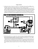
Vacuum Switch – This boiler is equipped with a vacuum switch that is designed to prevent burner operation if the
combustion fan does not operate properly or there is a blockage in the vent system. This switch “makes” (permits
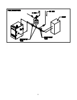
burner operation) as the vacuum increases. Figure 40 shows the correct method of reading the switch vacuum. The
vacuums in Table 9 are the minimums required for reliable operation. After the boiler fires, the vacuum will drop for
several minutes before stabilizing. The vacuum shown under “Burners On” in Table 9 is the minimum reading which
should be observed after the vacuum has stabilized. The Table 9 readings correspond to sea level vacuum switch
settings. Consult your Crown representative for possible variations in settings at altitudes over 2000ft.
MODELS
BURNERS ON
BWF061, BWF095
-0.57
-0.51
BWF128, BWF162
-0.96
-0.89
BWF195, BWF229
-1.21
-1.14
TABLE 9: MINIMUM. VACUUM SWITCH
READINGS (in. W.C.)
DURING
PREPURGE
Summary of Contents for BWF061
Page 8: ...7 ...
Page 9: ...8 ...
Page 14: ...13 ...
Page 31: ...30 ...
Page 34: ...33 ...
Page 36: ...35 ...
Page 40: ...39 FIGURE 38 PILOT BURNER FLAME ...
Page 49: ...48 ...
Page 51: ...50 1 Burner Components 50mm Burner Components ...
Page 53: ...52 ...

