background image


Radio system instructions

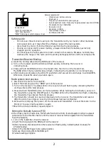
     Caution

1

To prevent serious personal injury and/or property damage,operate all remotely

controlled models in a responsible manner as outlined herein.


Safety Precautions

1.1 This radio-controlled model is not a toy, it is designed for persons 14 years of age or older.

1.2 Do not operate your vehicle on unsafe terrain; always pay attention to your surroundings.

1.3 Never operate your vehicle on public roadways, around moving people, animals, or operating machinery.

1.4 Keep clear of power lines and high-powered radio equipment to minimize radio frequency interference.

1.5 Since this vehicle contains small components, it may be a choking hazard for small children. Keep the vehicle and

     any spare parts out of reach of small children.


 Inspect your radio-controlled model before operation

2.1 Ensure that all screws are properly tightened. Use thread-lock to secure any metal to metal contacts- especially for components designed

      to withstand torque (servo mounts, motor mount, drive shaft grub screws etc.).

2.2 Always check the battery voltage for both the transmitter and vehicle prior to operating your vehicle. Keep the batteries fresh in the

     transmitter and always begin your vehicle runs with a fully charged battery pack.

2.3 Always check that the motor and servo are operating smoothly and in the right direction prior to operation. If binding  between

   components is observed, replace parts as necessary to reduce possibility of component or servo damage.

2.4 To turn on your vehicle, always power on your transmitter first, then power on your receiver.


After operating your radio-controlled model

3.1 To turn off the vehicle, always power off your receiver prior to powering off your transmitter.

3.2 Use caution when handling the vehicle- components, especially the ESC and motor which will be hot after operation.

3.3 Never use battery packs which are dented or otherwise damaged. Ensure that the wire insulation is intact and that connectors are

      properly soldered. Lithium batteries can become fire hazards if mishandled.

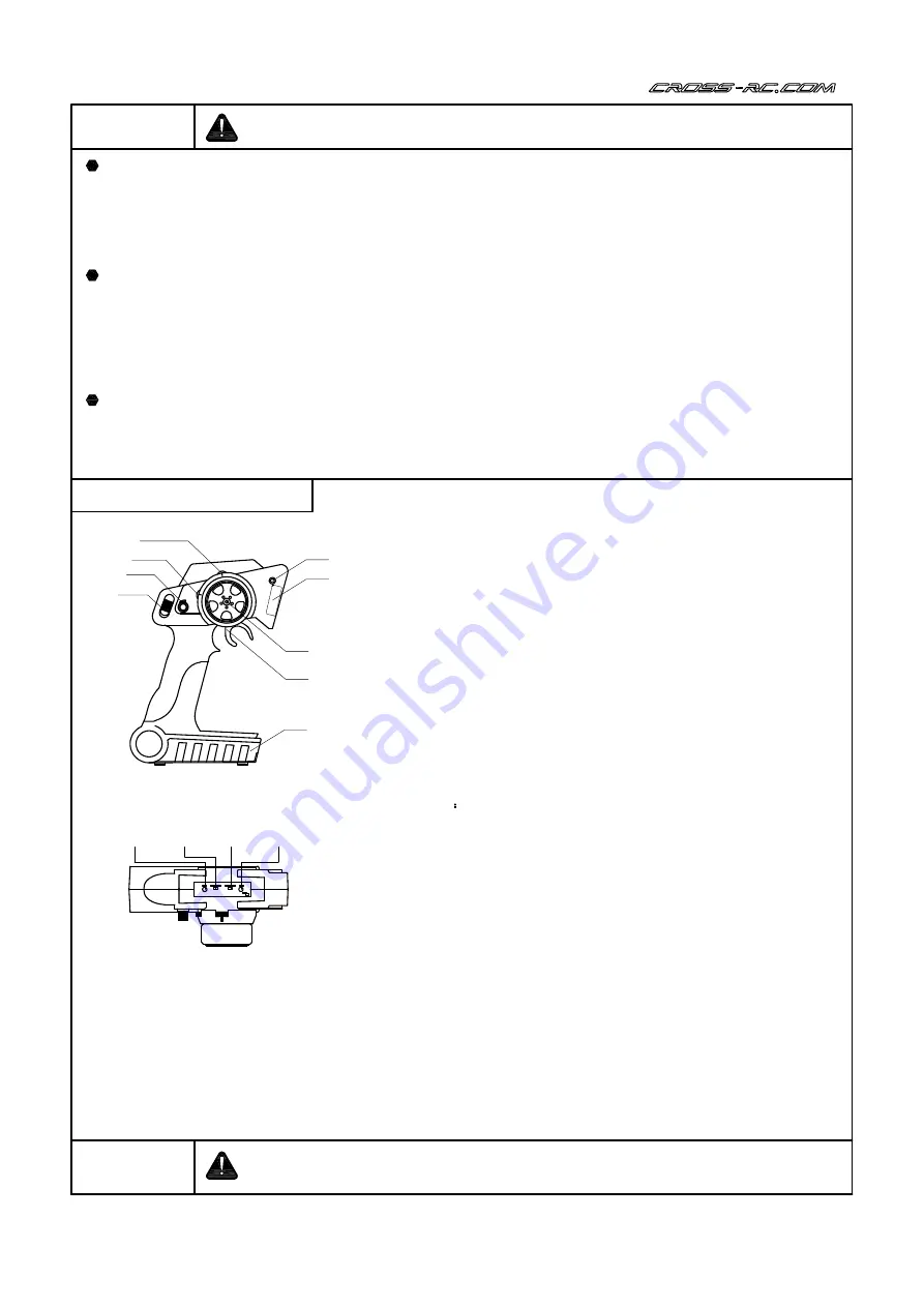
A

B

C

D

E
F

G

H

I

J

K

L

M

A. On/Off switch: Ensure that the throttle and steering channels

     are at their neutral position prior to turning on the transmitter.

B. Steering rates: Increases or decreases the maximum steering

    servo deflection.

C. Throttle trim: Adjusts the neutral position of the throttle output.

D: Steering trim: Adjusts the neutral position of the steering servo.

E: Bind button: Used for binding the transmitter to the receiver.

F: Antenna: An internal 2.4GHz antenna is located at this position.

G: Steering wheel: Proportional control for the steering servo.

H: Throttle trigger: Proportional control for the ESC and motor output.

I: Battery compartment: Accepts 4x 

AA

 batteries.

J: Power LED: Flashes when battery voltage is low.

K: Steering reverse: Reverses the direction of travel for the

    steering servo.

L: Throttle reverse: Reverses the direction of travel for the

    motor output  .

M:  Bind LED  Flashes during the binding process.

   Caution

Do not obstruct the antenna cover as it may reduce the operating range of

 the radio system.

Transmitter Specifications

-

Intended use: Surface vehicles

-

Number of channels: 2

-

Frequency: 2.4GHz ISM Frequency range

-

Spread spectrum mode: Frequency hopping spread- spectrum (FHSS)

-

Modulation format: FSK/GFSK

-

Output power: <100mW

-

Operating current < 150mA

-

Resolution: 1024uS

-

Proportional throttle and steering controls

-

Steering servo dual rates

-

Throttle EPA

-

Low voltage warning

-

Fail safe protection

-

Certificates: CE/FCC

Summary of Contents for CZRFR4RTR

Page 1: ... the vehicle always power off your receiver prior to powering off your transmitter 3 2 Use caution when handling the vehicle components especially the ESC and motor which will be hot after operation 3 3 Never use battery packs which are dented or otherwise damaged Ensure that the wire insulation is intact and that connectors are properly soldered Lithium batteries can become fire hazards if mishan...

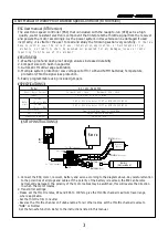
Page 2: ...tter and receiver should change to solid GREEN Otherwise repeat the above operation again Setting the Fail safe function F S In the unlikely event of radio loss the fail safe function built into this radio system will give a preset output value to the throttle channel until the receiver receives further signals from the transmitter To set the fail safe 1 Turn on the transmitter then the receiver 2...

Page 3: ...ed this will reverse the direction in which the motor rotates 2 Transmitter settings Please set the throttle rates ATL and EPA to 100 to give the throttle channel maximum travel range where applicable Set the throttle trim to neutral Reverse the throttle channel on Futaba radios for all other radios set the throttle channel reverse to NOR or Normal Set the fail safe function Refer to the instructi...

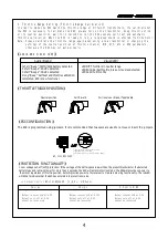
Page 4: ...D Solid Full throttle THROTTLE TRIGGER POSITION PROTECTION FUNCTIONALITY ESC CONFIGURATION The ESC is programmed using jumpers It is recommended that tweezers are used to remove or insert the jumpers 1 Low voltage cut off LVC protection If the voltage of the battery pack is lower than the preset thresholds for the detected battery type and remains lower for more than 2 seconds the ESC will enter p...

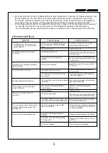
Page 5: ...he motor turns in a direction opposite to the throttle input Motor polarity is reversed Swap the two wires that connect the ESC to the motor The truck is unable to reverse The jumper position is incorrect Check the jumper and insert it into the correct position The neutral point of the throttle channel has changed Set the throttle trim to 0 then perform an automatic calibration The truck can only ...

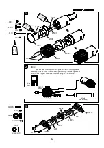
Page 6: ...embly If the gearbox is not operating smoothly or is creating excess noise check the gear mesh prior to proceeding to the next step 3 11116 M2 5x12 11116 200201 200202 5x 11x4 15006 5x 8x0 3 72007 41292 72007 15006 72007 15006 6 THREAD LOCK THREA D LOCK Electronics speed control Black Red White ON OFF Switch Battery Not included s TH ST BIND BT R2 MADE IN CHIAN ON OFF ...

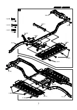
Page 7: ...4 11206 M3x8 11206 11108 11106 M3x8 11106 11106 11206 11108 204206 71116 71117 204207 204404 204403 73044 204303 204405 7 11108 M3x12 ...

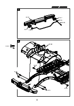
Page 8: ...5 8 21217 21217 87078 Yellow Yellow 6 201504 11106 M3x8 11106 11106 11106 11106 200910 ...

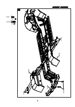
Page 9: ...7 M3x8 11303 11106 M3x8 11106 11106 11303 204301 204302 9 205008 ...

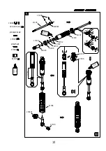
Page 10: ...OCK OIL 17007 17008 Ø6 5xØ2 5xØ2 Ø7xØ5xØ1 13004 2 0x 5 5x0 4 13004 200501 41197 41418 42312 42313 17007 41196 17007 200103 41198 17008 41195 41336 41368 200401 41336 10 SHOCK OIL 8 x4 x4 SHOCK OIL 28 5mm ...

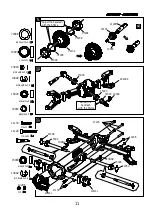
Page 11: ...15x4 13003 72007 72008 13002 15003 15003 72007 13002 202002 Adjust the backlash with the Shims 9 x2 10 Ø5xØ8x0 3 Ø5xØ10x4 Ø3 8xØ9 2x0 6 Ø2 5xØ6 2x0 4 Ø10 2xØ15x0 2 11133 202001 201901 11120 15003 15003 41248 41250 12206 13002 Ø3 8xØ9 2x0 6 13002 13002 11 M2 12206 11120 11133 M2x12 15003 Ø5xØ10x4 M2 5x20 ...

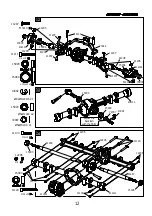
Page 12: ...1205 202004 15004 11207 41208 41208 12 13 15003 15003 72007 13002 Adjust the backlash with the Shims 15003 72007 13002 202102 11120 M2 5x20 11133 11133 11120 15003 15003 41249 15003 41247 202101 201901 14 12206 12206 12206 11133 M2x12 M2 12206 GREASE Ø5xØ10x4 x2 Ø 8xØ9 2x0 6 X1 Ø5xØ8x0 3 x1 M3x18 11111 12 12 ...

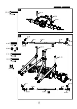
Page 13: ...41143 11407 41336 x2 200103 41336 200103 11407 11407 41125 x2 M3 12203 12203 41336 16 95mm 80 5mm 41336 200102 41336 200103 M3x18 11111 11111 95m m 80 5mm 8 0 5 m m 9 5 m m 11111 11114 11114 11114 M3x25 M3x18 11111 11111 73042 ...

Page 14: ...201602 M3x8 11303 11303 71025 11206 M3x8 11206 11409 11409 M4x11 95033 18 THREAD LOCK 17 14 12203 12203 M3 12203 204208 204208 11114 M3x25 11114 11114 11117 M3x30 11117 11117 ...

Page 15: ...41336 11107 3x 7x0 5 14102 14102 14102 11107 M3 12203 12203 11106 27407 27407 11114 11111 11109 SERVO M3x10 11107 M3x8 11106 M3x14 11109 100mm 51 5mm 15 19 51 5mm 100mm 12203 M3x18 11111 11114 M3x25 12203 Turn on the Transmitter then Receiver and set the Steering Servo Trim at the neutral position 20 ...

Page 16: ... 12203 12203 200102 41336 11409 M4x11 M3 12203 41164 21 100mm 86 5mm THREAD LOCK 41336 200103 1 0 0 m m 8 6 5 m m 86 5m m 100m m 11114 M3x25 M3x18 11111 11114 11114 11111 THREAD LOCK 11212 M3x20 M3x20 11112 12203 12203 12203 12203 11409 95033 11112 11112 11212 11212 41164 41164 22 71160 71160 ...

Page 17: ...17 23 11303 41613 52 5m m M3x8 11303 M3x20 11112 11114 M3x25 11409 M4x11 THREAD LOCK 41164 11112 11112 41164 41164 11114 11114 11409 41613 THREAD LOCK ...

Page 18: ...18 41613 52 5m m 11114 M3x25 11409 M4x11 THREAD LOCK 11114 11114 11109 11109 41613 24 11409 M3x14 11109 Left Right THREAD LOCK ...

Page 19: ...19 M3x12 11108 11108 201601 M4x4 11405 11409 M4x11 11405 11409 95034 THREAD LOCK 25 26 11106 M3x8 11106 11106 THREAD LOCK THREAD LOCK ...

Page 20: ...27 20 11106 M3x8 11106 11106 M3x8 11303 11303 11303 11106 11106 M3x14 11109 11109 42310 42310 204401 204402 202410 202410 202409 94015 94015 94015 91004 91004 206308 Ø11xØ5x5 206308 Ø11xØ5x5 ...

Page 21: ...02 21 M4 12204 x4 28 29 Direction of rotation M2x6 11102 25701 50010 42318 25801 11102 Apply instant cement Apply instant cement Apply instant cement x2 Direction of rotation 25701 50010 42318 25801 11102 Apply instant cement x2 11412 M3x3 11412 ...

Page 22: ...h PCB left 87078 BLACK RED PCB right 31 Black Red White Servo ON OFF Switch PCB left 5mm LED Yellow BLACK RED PCB right Bumper Taillight 87079 Motor Battery 29 30 ABS CEMENT A B S C E M E N T 205009 205010 85110 Not included s TH ST BIND BT R2 MADE IN CHIAN ON OFF ...

Page 23: ...M2x4 11101 11101 87079 GLUE 71153 202303 201407 201408 23 29 33 200802 73046 73045 200801 M2x6 11102 11102 11102 32 ...

Page 24: ...37 85112 204203 204204 M3x8 11303 11303 11207 M3x10 11207 24 UP 35 34 ...

Page 25: ...36 25 B A T T E R Y N o t i n c l u d e d ESC Receiver ...

Page 26: ...26 94015 94015 37 ...

Page 27: ...27 ...

Page 28: ... Cap screw 2 97400531 FR4 Suspension battery box 1set 204304 Battery box 1 1 204403 Battery box rear bracket 1 204404 Battery box front left bracket 1 204405 Battery box front right bracket 1 91004 Battery binding band 2 11206 Flat head screw 2 11108 Cap screw 2 11303 Sunk screw 3 97400405 Wheel Arch 1 pcs 201504 Wheel arch 1 1 97400530 FR4 Rear wheel arch 1 set 204301 Left arch 1 1 204302 Right a...

Page 29: ...sing and Steering Knuckles G2 1 set 201901 G2 diff cover 1 1 202001 G2 front axle housing 1 1 202002 G2 front axle housing 2 1 202003 G2 right steering knuckle 1 202004 G2 left steering knuckle 1 97400379 G2 Rear Axle Housing 1 set 202101 G2 rear axle housing 1 1 1 202102 G2 rear axle housing 2 1 201901 G2 diff cover 1 97400418 Front Axle Hardware Set 1 set 11120 M2 5 20 cap screw 4 1 11133 M2 12 ...

Page 30: ...ew 4 94015 Φ6 R Buckle 6 97400544 FR4 Transparent lens assembly 1 set 201407 Left lampshade 1 1 201408 Right lampshade 1 21217 Trailer taillight 2 97400548 FR4 Scale spare tire assembly 1 set 204203 Spare tire bracket A 1 1 204204 Spare tire bracket B 1 205002 Spare tire cover 1 205003 Spare tire holder 1 11303 Sunk screw 2 11207 Cap screw 2 97400356 Chrome Main Grille 1 set 11102 M2 6 Cap screw 4...

Page 31: ... Axle Assembly 1 set 97400382 G1R Complete Rear Axle Assembly 1 1 97400508 SP4 FR4 SU4 Stamping hub 1 set 71156 Hub inner frame 2 2 71157 Hub outer frame 2 41375 Iron compressing ring 2 30307 Wheel disc adapter herringbone 2 11120 Cap screw 2 11116 Cap screw 14 12105 Hex nut 14 97400509 SP4 FR4 CNC hub 1 set 44083 CNC wheel cover 2 2 44084 CNC wheel bottom cover 2 41375 Iron compressing ring 2 205...

Page 32: ...er 1 205110 Right lamp holder 1 205111 SP4 handle 2 97400547 FR4 Off road auxiliary lamp Need to have 97400533 1 set 204103 Anti rolling top lamp holder 1 1 201706 Light holder 4 201704 Light shade 4 201403 Spot light lens 4 75008 Spot light retaining bar 1 87069 SG4 body light plate kit 1 11202 M2 6 4 11133 Cap screw 4 11205 M3 6 4 32 D223F Metal geer Digital servo Transmitter BT T2A Recriver BT ...

Reviews: