Cross Technologies 2083-1919-02 Instruction Manual Download Page 13

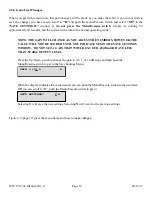
2.5.2.  Power On Settings

NOTE: THE LAST OPERATING PARAMETERS OF A UNIT ARE RETAINED EVEN WHEN 

POWER IS  REMOVED.  WHEN POWER IS RESTORED, THE  UNIT  WILL RETURN TO IT'S 
PREVIOUS SETTINGS.

When  power is first applied, the LCD display goes through three steps.

1. The LCD goes black to show all segments are functioning.
2. The Model and Software version will be displayed.

2083-1919-02
Rev. 1.00

3. The present frequency and gain of the upconverter is shown.

FC = 1350        
G=+10.0  REF  AUTO-I

The  unit  is  now  operational and ready  for  any  changes  the operator may desire.

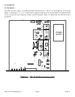
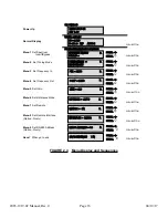
2.5.3  Control Switches

1. Menu/Execute - Any change to the programming of the  unit must be initiated by pressing the 

Menu/Execute switch and completed by pressing the Menu/Execute switch.

2. Horizontal Switch - This switch is mounted so its movement is horizontal and moves the 

display cursor left or right.  

3. Vertical Switch - This switch is mounted so its movement  is vertical and has two functions:

a. During gain changes,  the  vertical movement will raise or lower the number 

in the direction of the arrows.

b. For  other functions such Remote on/off, the  vertical  switch will alternately turn the function 

on or off regardless of the direction operated.

2083-1919-02 Manual, Rev. 0


 Page 13


         04/19/17

Summary of Contents for 2083-1919-02

Page 1: ...be reproduced or duplicated without the prior permission of Cross Technologies Inc for purposes of operating the equipment Printed in USA When ordering parts from Cross Technologies Inc be sure to in...

Page 2: ...to customer Cross Technologies Inc s obligation under this warranty is limited to repairing or at Cross Technologies Inc s option replacing parts subassemblies or entire assemblies Cross Technologies...

Page 3: ...External 10 MHz reference which appear on the LCD display and can be adjusted remotely Front panel LEDs provide indication of DC power green PLL alarm red and remote operation yellow Connectors are T...

Page 4: ...cy Response 10 to 20 dB 2 dB Selectable in 0 5 0 5 dB steps Gain Fc 1 2 1 7 GHz 250 MHz Frequency 75 12 dB Impedance RL 10 dBm Input maximum no damage 50 to 30 dBm Input Composite Level 950 1950 MHz F...

Page 5: ...NC RF OUT D 75 BNC RF IN 75 BNC RF OUT B Contact Cross Technologies for other options 2017 Cross Technologies Inc Connectors Impedance Ethernet with TCP IP Telnet W28 Ethernet with Web Browser and SNM...

Page 6: ...male DB 9 PC Com Port Male DB 9 2015 16 17 M C Port M C Cable Diagram Cross Technologies Frequency Converters RX RX TX TX DTR SG DSR RTS CTS SG Connector Rear panel DB 9 male J10 Pinouts RS 232C 422 4...

Page 7: ...n Independent Input Output Frequency Tuning mode x 1 if in Tracking mode Frequency Out Frequency In Gain aaSG Returns aaSGxxx where xxx RF gain in dB range 100 to 200 example if xxx 155 then the unit...

Page 8: ...x 1200 1700 1 MHz Steps Set Output Frequency aaCFxxx where xxx 1200 1700 1 MHz Steps Set Tuning Mode aaCMx where x 0 for independent Input Output Frequency Tuning x 1 for Tracking Mode Frequency Out F...

Page 9: ...6 inch deep chassis A switching 12 24 5 VDC power supply provides power for the assemblies The 2083 1919 02 can be secured to a rack using the 4 holes on the front panel Figure 2 0 shows how the 2083...

Page 10: ...utput Connector Options Connector Options Option Input Output B BNC 75 BNC 75 D BNC 50 BNC 50 NN N 50 N 50 Remote Serial Interface Interface DB 9 Male Protocol RS 232C RS 232C 422 485 option Q 9600 ba...

Page 11: ...el provided See Section 2 5 Menu Settings 5 Be sure DS6 green DC Power is on and DS2 red Alarm is off Figure 2 2 6 AC Fuse The fuse is a 5 mm X 20 mm 2 amp slow blow Type T and is inserted in the far...

Page 12: ...ace Option Q only Menu 9 Set RS 485 Address Option Q only Save Menu When R is selected from any above menu or at the end Alarm indications appear on the LEDs see Figure 2 2 All program changes must st...

Page 13: ...hanges the operator may desire 2 5 3 Control Switches 1 Menu Execute Any change to the programming of the unit must be initiated by pressing the Menu Execute switch and completed by pressing the Menu...

Page 14: ...T BE STORED UNTIL YOU INDICATE YES IN THE SAVE SETTINGS WINDOW DO NOT SET A GAIN THAT WOULD EXCEED 20 dBm OR HAVE LESS THAN 50 dBm OUTPUT LEVEL Press the Up Down switch to change the gain in 0 5 1 or...

Page 15: ...e External Reference is present on the Reference Output connector J8 Auto Mode The unit defaults to the External 10 MHz Reference as long as the level meets the 3dBm 3dB specification REF AUTO E appea...

Page 16: ...ion Q only Menu 9 Set RS 485 Address Option Q only Save When go to end SCROLL SCROLL PUSH BUTTON SCROLL SCROLL PUSH BUTTON SCROLL SCROLL PUSH BUTTON R SCROLL SCROLL PUSH BUTTON GAIN 20 REMOTE ON INTER...

Page 17: ...operation of the equipment is not compromised Additional space between units may be required E Circuit Overloading Consideration should be given to the connection of the equipment to the supply circu...

Page 18: ...NC 6170 Shiloh Road Alpharetta Georgia 30005 770 886 8005 FAX 770 886 7964 Toll Free 888 900 5588 WEB www crosstechnologies com E MAIL info crosstechnologies com Printed in USA 2083 1919 02 Manual Rev...

Reviews: