background image

Measurement Polarity

The measuring current polarity may be selected from the front panel. The display will indicate 
or - to denote the current fl ow. This is particularly useful when evaluating circuits with 
thermal emf or where diode effects can infl uence the measurement. For measurements where 
thermal emf can cause a large measuring zero error, we have provided an additional automatic 
average button. When pressed, the measuring current will automatically be reversed and the 
average value displayed, thus eliminating the need for external computations. This average 
facility will also adjust the measurement time automatically, thus giving the fastest possible 
measurement even on inductive circuits.

The +ve and -ve lamps will light to indicate that the current polarity is changing. For very 
unstable values where the average mode is unable to establish a stable reading, the averaging 
will be aborted after approximately 25 seconds and the display will indicate - - - - A new 
average cycle will be automatically initialised.

Range Selection:

The 6 ranges may be selected manually by simply pressing the desired range button. The 
selected range will be indicated by an LED and over-range will be indicated by the display 
reading - - - -. An Auto range facility is also provided, pressing the AUTO key sets the DO7e in 
to auto range mode.

Error & Status Lamps

These LEDs will light to indicate the instrument status.

LINE  

Mains supply is connected to the instrument.

LOBAT  

:  

Indicates low remaining battery capacity

CHG  

:  

Indicates that the internal battery is charging

O/C  


One of the measuring leads is open circuit

LEAD  

:  

(too high resistance), or not connected to


test sample correctly, or the internal protection


fuse is open circuit. The lamp will always


light in standby mode.

9.  

METHODS OF MEASUREMENT

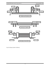
9.1   Ohmmeter Connections

The Digital Ohmmeter type DO7e employs a four wire method of measurement, ie. it is 
necessary to make four connections to the resistor under test. The instrument is supplied with 
four leads; two for the potential connections which are made across the test resistor at the 
points between which the resistance is to be determined; and two for the current connections 
which connects the test resistor to the supply circuit.


a)  

Connect the black leads to the +I and +U terminals, and the red leads to terminals 


-I and -U.


b)  

Clip on to the resistor under test (fi g. 9-1). Cleanliness is important and if the sample


is not clean, a rub with an abrasive paper to remove oxides is recommended.

Digital Microhmmeter Type DO7e

Operating Instructions

8

Summary of Contents for DO7e

Page 1: ...en Hill South West Industrial Estate Peterlee Co Durham SR8 2SW England Tel 44 0 191 586 3511 Fax 44 0 191 586 0227 www cropico co uk sales cropico co uk Digital Microhmmeter Type DO7e Operating Instructions ...

Page 2: ......

Page 3: ...ocopying recording or in any manner without prior written consent from CROPICO This also applies to accompanying drawings and diagrams Due to a policy of continuous development CROPICO reserves the right to alter the equipment specification and description outlined in this publication without prior notice and no part of this publication shall be deemed to be part of any contract for the equipment ...

Page 4: ...rise yourself with the appropriate local separate collection system for electrical and electronic products Please dispose of this product according to local regulations Do not dispose of this product along with normal waste material The correct disposal of this product will help prevent potential negative consequences for the environment and human health User Note These Operating Instructions are ...

Page 5: ... 8 DESCRIPTION OF CONTROLS 7 Range Selection 8 Error Status Lamps 8 9 METHODS OF MEASUREMENT 8 10 POWER UP 11 11 MEASUREMENT 11 Current Mode 11 Over Range 11 Low Battery 12 12 Connections 12 13 REMOTE 12 14 PROTECTION 12 15 CALIBRATION PROCESS 12 16 EQUIPMENT REQUIRED 13 17 PREPARATION 13 18 CALIBRATION 13 19 USING DISCRETE RESISTANCE STANDARDS 14 Digital Microhmmeter Type DO7e Operating Instructi...

Page 6: ...protective action must not be negated by the use of an extension lead without a protective conductor WARNING Any interruption of the protective conductor inside or outside the apparatus or disconnection of the protective earth terminal is likely to make the apparatus dangerous Intentional interruption is prohibited When the apparatus is connected to its mains supply terminals may be live and the o...

Page 7: ...achieved by using Specially selected components 4 CASE DESIGN The case is ruggedly constructed from an ABS polycarbonate alloy coloured safety yellow A strong internal sub frame ensures that the DO7e will withstand the harshest of environments The front panel is a reverse printed polycarbonate overlay with clear and unambiguous text 5 MAINTENANCE Normally no maintenance is required other than clea...

Page 8: ...trument to mains supply after use and top up battery Instruments should be stored with batteries fully charged and when stored for long periods the batteries should be recharged each month Should the batteries become deeply discharged due to being left for long periods without charge then the internal charger will automatically sense the battery state and will trickle charge with a very low curren...

Page 9: ...me Approx 0 5 seconds Polarity Forward and reverse measurement current may be selected plus average mode which automatically displays the average value of positive and negative polarity measurement Ranges and Accuracy NOTE Temperature coefficient to be added to uncertainty when operating outside the range 15 to 25 C NOTE Measurements on the lowest range 60µΩ may have an additional zero offset of u...

Page 10: ...y CAL Key Current Mode Keys Measure Key Remote Start Socket 8 DESCRIPTION OF CONTROLS Digital Microhmmeter Type DO7e Operating Instructions 7 Measuring Terminals 4 Digit LCD Display Remote Start Socket Measure Key Current Mode Keys CAL Key OFF Key On Key Auto Range Key Mains Socket ...

Page 11: ...LED and over range will be indicated by the display reading An Auto range facility is also provided pressing the AUTO key sets the DO7e in to auto range mode Error Status Lamps These LEDs will light to indicate the instrument status LINE Mains supply is connected to the instrument LOBAT Indicates low remaining battery capacity CHG Indicates that the internal battery is charging O C One of the meas...

Page 12: ...pecial test fixtures may have to be made for the user to suit particular applications d Fig 9 2 illustrates connections to various types of test resistors e When measuring 4 terminal resistance standards do not use the combined current and potential probes Make four separate connections to the current and potential terminals Digital Microhmmeter Type DO7e Operating Instructions 9 ...

Page 13: ... P2 U Connections to Current Shunt C1 I C2 I P1 U P2 U Fig 9 2 Various types of resistors Digital Microhmmeter Type DO7e Operating Instructions 10 C1 I C2 I P2 U P1 U Connections to Stud Terminals C1 I P1 U P2 U C2 I Connections to Cable Joint Connections to Current Shunt C1 I P1 U C2 I P2 U ...

Page 14: ...AS key should be pressed again Should you wish to initialise a continuous reading then press and hold the MEAS key until a long bleep is heard this will lock the measurement in continuous mode Note continuous measurement is not possible on the lowest 6mΩ range The measurement will continue until the MEAS key is pressed again The DO7e will automatically power off after 5 minutes with no key activit...

Page 15: ...ng applied to the terminals A large 6 Amp fuse is fitted internally to the C measuring line and a gas discharge tube GDT is across the C terminals If voltages above approximately 90V are applied to the measuring terminals the GDT will strike effectively shorting the C terminals through the 6 Amp protective fuse which will interrupt the circuit The fuse fitted will interrupt up to 40 000 Amps The P...

Page 16: ...wer ON whilst holding down the CAL key 17 6 Leave for a few minutes to stabilise 18 CALIBRATION ENTERING A PASSCODE CALIBRATION 1 Hold down CAL key whilst powering up the DO7E displays CODE 2 Enter the 4 digit passcode default is 9252 and press OK 3 If the code was incorrect a long beep is emitted and the user should start again from 2 4 If correct the DO7e displays zero eg 0 0 and is now in Calib...

Page 17: ...PASSCODE 1 Carry out 1 to 4 as above using the existing passcode 2 Press and hold the CLE key for 2 seconds the DO7e displays CODE 3 Enter the new 4 digit passcode and press OK the DO7e displays CODE again 4 Re enter the new 4 digit passcode and press OK 5 If the new passcode was not entered correctly both times a long beep will be emitted and the process must be repeated from 3 6 If correct the D...

Page 18: ... ZERO measurements connect the C1 and C2 leads to the C2 terminal of the standard see Fig 20 2 FULL SCALE CALIBRATION P1 P2 LEADS PURE COPPER MULTI STRANDED C1 C2 LEADS 10A RATING 55 0 15MM Fig 20 1 ZERO CALIBRATION P1 P2 LEADS PURE COPPER MULTI STRANDED C1 C2 LEADS 10A RATING 55 0 15MM Fig 20 2 END OF TEST PROCEDURE Digital Microhmmeter Type DO7e Operating Instructions 15 C1 P1 P2 C2 C1 P1 P2 C2 ...

Page 19: ...clamp options Description Duplex Handspikes with 2 5 metre lead length current and potential spikes suitable for plate or Bussbar measurements Duplex Handspikes as a HS01 P but with 2 5 and 15 metre lead lengths Large Kelvin clips with 3 metre lead length suitable for attaching to rods bars or cables up to 38mm diameter As LS03 P but with lead lengths 3 and 15 metres Executive lead set consisting ...

Page 20: ...61010 2 030 2010 Safety requirements for electrical equipment for measurement control and aboratory use Part 2 030 Particular requirements for testing and measuring circuits BS EN61326 1 2006 Electrical equipment for measurement control and laboratory use EMC requirements Part 1 General requirements Performance The instrument operates within specification when used under the conditions in the abov...

Page 21: ...ntact Tel 44 0 191 587 8718 For Service and Calibration Contact Service Department Seaward Group Unit 11 Bracken Hill South West Industrial Estate Peterlee Co Durham SR8 2LS England Tel 44 0 191 587 8739 Fax 44 0 191 587 8737 E mail service seaward co uk CROPICO is a division of ...

Page 22: ...SISTANCE STANDARDS DIGITAL THERMOMETERS THERMOCOUPLE SIMULATORS PT100 SIMULATORS INSULATION TEST SETS UNIVERSAL CALIBRATORS HIPOT TESTERS ELECTRICAL SAFETY TESTERS Phone fax or e mail for further information on the above or for a copy of our general catalogue Phone 44 0 191 5863511 Fax 44 0 191 5860227 E mail sales cropico com Website www cropico com ...

Page 23: ......

Page 24: ...610019 Rev 5 ...

Reviews: