background image

Crestron 

TMK-15L & WMKT-15L


Trim Ring Mount Kits


Installation 

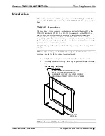
This section provides an installation procedure for each Trim Ring Mount Kit. The 
procedure for the TMK-15L starts below and the “WMKT-15L Procedure” starts on 
page 4. 

TMK-15L Procedure 

The procedure in this section provides the necessary steps for the assembly of the 
TMK-15L to either the PMK-15L or BB-15L. It is assumed that the PMK-15L or 
BB-15L has been secured to the stud according to the procedures in the latest 
revisions of their respective Installation Guides (Doc. 6363 and Doc. 6362, 
respectively). Also, it is assumed that drywall is in place and a rectangular cutout for 
the touchpanel is made in the drywall (refer to the Drywall Cutout dimensions in the 
previous diagram for cutout dimensions). 

Complete the steps in the order provided. The only tool required and not supplied is 
a level.  

NOTE:  

When installing into the PMK-15L, verify that the 18 AWG bus wire 

securing the cables for the touchpanel remains attached.  

1.  Verify that the rectangular cutout in the drywall is as level as possible. 

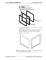
2.  Insert the symmetrical trim ring into the opening, as shown in the following 

diagram.  

Insert Trim Ring into Opening 

TRIM RING

(2013004)

IMPORTANT
PLEASE MAKE DRYWALL CUTOUT AS
LEVEL AND CLEAN AS POSSIBLE.
THE MOUNTING PLATE ALLOWS FOR ONLY
MINOR ADJUSTMENT OF THE TOUCHPANEL


NOTE:

  The required PMK-15L or BB-15L is not shown. 

Installation Guide – DOC. 6365 

Trim Ring Mount Kits:  TMK-15L & WMKT-15L  

  3 

Summary of Contents for TMK-15L

Page 1: ...Crestron TMK 15L WMKT 15L Trim Ring Mount Kits Installation Guide ...

Page 2: ...n by the Technical Documentation department at Crestron Electronics Inc 15 Volvo Drive Rockleigh NJ 07647 1 888 CRESTRON All brand names product names and trademarks are the property of their respective owners 2005 Crestron Electronics Inc ...

Page 3: ...s to framed walls prior to hanging drywall This accessory must be used with either the Pre Construction Mount Kit PMK 15L or Back Box Kit BB 15L The WMKT 15L is a post construction kit Post construction refers to framed walls with drywall hung This accessory is designed with a mounting plate so that it can be placed anywhere on a wall without the support from a stud The mounting plate is also idea...

Page 4: ...cm MOUNTING PLATE FOR WMKT 15L 13 01 in 33 05 cm 2 20 in 5 59 cm TRIM RING 14 19 in 36 05 cm 0 06 in 0 15 cm 13 79 in 35 02 cm Drywall Cutout Dimensions 137 64 in 333 mm Max DO NOT EXCEED THIS DIMENSION 1261 64 in 329 mm Max 123 4 in 324 mm Max 5 64 in 2 mm Max 3 16 in 5 mm Max Ø 3 16 in 5 mm Max TYP 4X 613 64 in 158 mm Max 131 2 in 343 mm Max DO NOT EXCEED THIS DIMENSION 321 32 in 93 mm Max 15 64...

Page 5: ...ular cutout for the touchpanel is made in the drywall refer to the Drywall Cutout dimensions in the previous diagram for cutout dimensions Complete the steps in the order provided The only tool required and not supplied is a level NOTE When installing into the PMK 15L verify that the 18 AWG bus wire securing the cables for the touchpanel remains attached 1 Verify that the rectangular cutout in the...

Page 6: ...order provided The only tools or materials required and not supplied are a drywall saw or equivalent and a level 1 Locate an area on the wall that is free of miscellaneous wiring and studs 2 Make a small hole near the middle of the designated site verify that the location is suitable NOTE Make the cutout as level and smooth as possible The mounting plate allows for only minor leveling adjustments ...

Page 7: ...h the opening and rest it against the interior surface of the drywall 6 When the mounting plate is in position bend the top two flanges of the trim ring upward approximately 90 degrees and the bottom two flanges downward approximately 90 degrees Refer to the following diagram Bend Flanges Front and Back View NOTE The mounting plate will have slight play this is normal It allows for minor adjustmen...

Page 8: ...les in the mounting plate Refer to the latest revision of the TPS 12L 15L 17L Operations Guide Doc 6355 the TPS 12G 15G L Operations Guide Doc 6356 or the TPMC 15 17 L Series Operations Guide Doc 6354 for details CAUTION Allow an air gap of at least 12 inches in the wall cavity above the touchpanel for heat dissipation 6 Trim Ring Mount Kits TMK 15L WMKT 15L Installation Guide DOC 6365 ...

Page 9: ...users will need to establish a user account to fully benefit from all available features As of the date of manufacture the TMK 15L and WMKT 15L have been tested and found to comply with specifications for CE marking Future Updates As Crestron improves functions adds new features and extends the capabilities of the TMK 15L or WMKT 15L additional information may be made available as manual updates T...

Page 10: ...nt lamps are not covered This warranty extends to products purchased directly from CRESTRON or an authorized CRESTRON dealer Purchasers should inquire of the dealer regarding the nature and extent of the dealer s warranty if any CRESTRON shall not be liable to honor the terms of this warranty if the product has been used in any application other than that for which it was intended or if it has bee...

Page 11: ...Crestron TMK 15L WMKT 15L Trim Ring Mount Kits Installation Guide DOC 6365 Trim Ring Mount Kits TMK 15L WMKT 15L 9 This page intentionally left blank ...

Page 12: ...Crestron Electronics Inc Installation Guide DOC 6365 15 Volvo Drive Rockleigh NJ 07647 2013141 Tel 888 CRESTRON 07 05 Fax 201 767 7576 Specifications subject to www crestron com change without notice ...

Reviews: