background image


This document was prepared and written by the Technical Documentation department at: 


Crestron Electronics, Inc. 

15 Volvo Drive 

Rockleigh, NJ 07647 

1-888-CRESTRON 


All brand names, product names and trademarks are the property of their respective owners. 

©2008 Crestron Electronics, Inc. 


Summary of Contents for SMK-6X

Page 1: ...Crestron SMK 6X SwivelMountKitforTPS 6X Installation Guide ...

Page 2: ...n by the Technical Documentation department at Crestron Electronics Inc 15 Volvo Drive Rockleigh NJ 07647 1 888 CRESTRON All brand names product names and trademarks are the property of their respective owners 2008 Crestron Electronics Inc ...

Page 3: ...res and Functions 1 Specifications 1 Physical Description 2 Setup 3 Supplied Hardware 3 Installation 3 Resources 9 Industry Compliance 9 Further Inquiries 9 Future Updates 9 Return and Warranty Policies 10 Merchandise Returns Repair Service 10 CRESTRON Limited Warranty 10 Installation Guide DOC 6577A Contents i ...

Page 4: ......

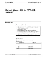
Page 5: ...ccommodates surface thickness from 3 4 inch 1 91 cm minimum to 1 3 8 inches 3 50 cm maximum using the hardware provided Cables route through center of assembly keeping cables completely hidden from work surface Customizable swivel range for added security and convenience Specifications Specifications for the SMK 6X are listed in the following table SMK 6X Specifications SPECIFICATION DETAILS Dimen...

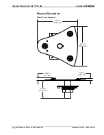
Page 6: ...or TPS 6X Crestron SMK 6X Physical Description SMK 6X Overall Dimensions 5 80 in 14 74 cm 6 09 in 15 45 cm 0 39 in 0 99 cm 0 44 in 1 11 cm 2 64 in 6 69 cm 2 Swivel Mount Kit for TPS 6X SMK 6X Installation Guide DOC 6577A ...

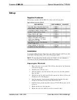
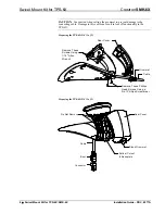
Page 7: ...l the assembly on a suitable mounting surface refer to the following procedures NOTE The mounting surface thickness must be 3 4 inch 1 91 cm minimum to 1 3 8 inches 3 50 cm maximum using the hardware provided Preparing the TPS 6X DS 1 Remove the four screws on the TPS 6X DS as shown in the first illustration on the following page 2 Carefully remove the rear cover 3 Slide the grommet out of the bot...

Page 8: ...ctionality in the TPS 6X Preparing the TPS 6X DS 1 of 2 Remove These Screws Using a 1 16 Allen Wrench Remove These Phillips Head Screws Using a No 1 Phillips Screwdriver Rear Cover Grommet Cable Preparing the TPS 6X DS 2 of 2 Do Not Remove Rear Cover Blank Grommet Bottom Cutout In Baseplate Cable Boot Connector 4 Swivel Mount Kit for TPS 6X SMK 6X Installation Guide DOC 6577A ...

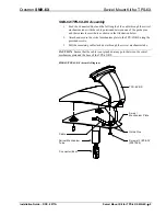
Page 9: ...ach and secure the swivel mechanism plate to the TPS 6X DS using the provided screws 3 Pull the remaining cable slack down through the swivel mechanism tube CAUTION Ensure that the cable is not pinched at any point between the swivel mechanism plate and the base of the TPS 6X DS SMK 6X TPS 6X DS Assembly Diagram Cable Swivel Mechanism Tube Connector Boot Swivel Mechanism Plate Guide Pins Screws 3 ...

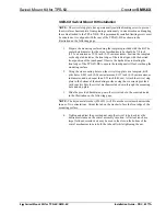
Page 10: ... overhang the mounting surface 2 Using the six mounting holes on the swivel stop plate as a template drill pilot holes 0 093 inch 0 24 cm minimum 0 115 inch 0 30 cm maximum in diameter and no deeper than 0 35 inch 0 89 cm Attach the swivel stop plate to the bottom of the mounting surface using the six screws provided with your kit Pass the swivel mechanism tube down through the mounting hole and s...

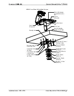
Page 11: ...nting Surface Front Edge Mounting Holes 6 In Swivel Stop Plate Swivel Stop Plate 4504353 Permanently Installed Limiting Screw Screws 2 08 32 2017634 Bottom Side of Table or Mounting Surface Screws 6 08 8B 2017784 Cork Rubber Washer 2017614 Keyed Metal Washer 4506321 Rubber Washer 2017615 Flat Steel Washer 2017633 Nut 7 8 14 Steel 2017632 Mounting Hole Installation Guide DOC 6577A Swivel Mount Kit ...

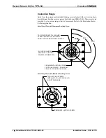
Page 12: ... below for their application Swivel Stop Plate with Permanent Limiting Screw TAB OF KEYED METAL WASHER STARTS SWIVEL MOTION FROM FRONT OF THE MOUNTING SURFACE SIX LOCATIONS FOR ADDITIONAL LIMITING SCREWS SYMMETRIC PERMANENT LIMITING SCREW POSITIONED AWAY FROM FRONT EDGE OF MOUNTING SURFACE 30 90 135 Swivel Stop Plate with Additional Limiting Screws TWO LIMITING SCREWS INSTALLED TO LIMIT SWIVEL TO ...

Page 13: ...tion of the Crestron website www crestron com onlinehelp to ask questions about Crestron products First time users will need to establish a user account to fully benefit from all available features Future Updates As Crestron improves functions adds new features and extends the capabilities of the SMK 6X additional information may be made available as manual updates These updates are solely electro...

Page 14: ...r 90 days batteries and incandescent lamps are not covered This warranty extends to products purchased directly from CRESTRON or an authorized CRESTRON dealer Purchasers should inquire of the dealer regarding the nature and extent of the dealer s warranty if any CRESTRON shall not be liable to honor the terms of this warranty if the product has been used in any application other than that for whic...

Page 15: ...Crestron SMK 6X Swivel Mount Kit for TPS 6X This page is intentionally left blank Installation Guide DOC 6577A Swivel Mount Kit for TPS 6X SMK 6X 11 ...

Page 16: ...Crestron Electronics Inc Installation Guide DOC 6577A 15 Volvo Drive Rockleigh NJ 07647 2018617 Tel 888 CRESTRON 07 08 Fax 201 767 7576 Specifications subject to www crestron com change without notice ...

Reviews: