Crestron SmarTouch STS Operation Manual Download Page 14

Programming Kit                                                                          Crestron 

ST-PK

10  

••

  STS Programming Kit: ST-PK

Operations Guide - DOC. 5662C

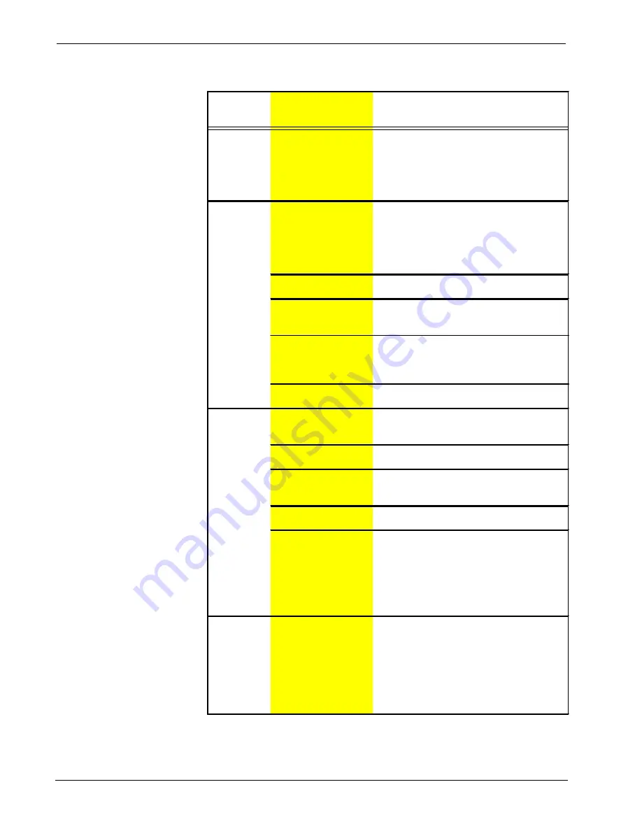
SmarTouch STS Troubleshooting (Continued)

TROUBLE

POSSIBLE 

CAUSE(S)

CORRECTIVE ACTION

RF LED on 
ST-CP 
illuminates, 
but COM or 
IR  LEDs do 
not illuminate.

Touchpanel RF ID is 
not set to match the RF 
ID assigned in the 
SmarTouch system  
program. 

Verify that RF ID match. Refer to "Configuring 
the Touchpanel" in the latest revision of the 
SmarTouch STS Touchpanels Operations 
Guide (Doc. 5803). 

RF LED on 
ST-CP does 
not illuminate 
when trying to 
control A/V 
equipment.  

Button on screen only 
has internal functions 
(i.e., join number 
equals 'NONE" or is 
greater than or equal to 
1000.

Reopen project and verify that button join 
number is between 1 and 999. 

NOTE:  

Can 

not assign join numbers to a border. 

ST-CP is not receiving 
power. 

Verify that the proper external AC power pack 
is attached to ST-CP. 

RF antenna is not 
securely attached to ST-
CP RF port. 

Verify that ST-CP RF antenna is properly 
attached. 

RF antenna is not 
properly located (i.e., 
inside a metal rack). 

Remotely locate RF antenna. Mount the 
antenna outside of the rack by using a 
bulkhead type BNC barrel and a BNC to BNC 
50 ohm cable. 

RF transmitter in 
SmarTouch is faulty.

Contact a Crestron technical  support 
representative. 

A/V device 
does not 
respond. 

STIRP or serial port not 
placed properly.

Verify placement of STIRP (Hold phosphor 
card under STIRP while pressing button) and 
tightness of serial cable.

Used wrong IR or serial 
port.

Verify proper IR or serial port is defined.

Wrong manufacturer or 
model number listed in 
SmarTouch system. 

Open the project in software and verify 
device definition.

Incorrect program is in 
control system.

Verify program is uploaded to control system 
with Performance Viewport from the software. 

Incorrect panel screens 
are in touchpanel. 

Use the software to open the project and 
verify that each button that is suppose to 
control the device has a join number and the 
command associated with it lists 
"SEND<device name> <function name>" 
(e.g., SEND LIV_RM_VCR PLAY). 

Download the touchpanel screens again. 

A/V device 
does not 
respond and 
wrong LEDs 
on ST-CP for 
device’s IR or 
serial port 
illuminate. 

SmarTouch system 
calls out wrong port or 
no port for device. 

Open SmarTouch system via software and 
change the port. 

Summary of Contents for SmarTouch STS

Page 1: ......

Page 2: ......

Page 3: ...uch STS Description 1 Software 2 Leading Specifications 3 Setup 4 STS Equipment 4 Applying Power 6 Identity Code 6 Preparing the System for Programming 7 Preparing the System for Operation 8 Problem Solving 9 Troubleshooting 9 Further Inquiries 11 Return and Warranty Policies 12 Merchandise Returns Repair Service 12 CRESTRON Limited Warranty 12 ...

Page 4: ......

Page 5: ...controlled from anywhere via the wireless user interface Users are no longer tethered by a wired control panel or limited to infrared line of sight control as with most ordinary wireless controllers There are six SmarTouch STS configurations available All configurations are functionally identical except for the touchpanel component which can be grayscale or color the type of input power required w...

Page 6: ...ystem include high clarity LCD touchpanel displays choice of custom icons and graphics touchpanel case is lightweight and contoured and easily held in one hand advanced Crestron RF technology allows complete freedom of movement up to 500 feet through walls indoors or outside touchpanel power options include rechargeable power pack or AC power supply control processor includes Cresnet network port ...

Page 7: ...creenCam movies for the Wizard are also available from the latest version of the Crestron ControlCD Let these movies demonstrate the simplicity of STS Wizard Learn how to use and get the most from Crestron software Leading Specifications The table below provides a summary of leading specifications for the SmarTouch STS and its primary components Dimensions and weight are rounded to the nearest hun...

Page 8: ... user is encouraged to try to correct the interference by one or more of the following measures n Reorient or relocate the receiving antenna n Increase the separation between the equipment and receiver n Connect the equipment into an outlet on a circuit different from that to which the receiver is connected n Consult the dealer or an experienced radio TV technician for help Setup STS Equipment The...

Page 9: ...System All Systems Delivers commands from control processor External AC PW 1205 STS or STS C Provides power to Power Pack PWI 1210 STSI STSI C STSI UK or touchpanel and control STSI C UK processor PW 1215 STS or STS C Provides power PWI 1215 STSI STSI C STSI UK or STSI C UK to ST DS The next table in this section shown below and on the next page lists some peripheral equipment that can be purchase...

Page 10: ...ument number This table does not account for the latest revision letter of each document Devices that Power the SmarTouch STS Touchpanel POWER OPTION NOMENCLATURE DOCUMENT NUMBER Domestic External AC Power Pack PW 1210 5762 International External AC Power Pack PWI 1210 5763 Docking Station ST DS 5738 Battery Pack ST BTP 5746 The control processor can only be powered via the appropriate external AC...

Page 11: ...NOT DRAWN TO SCALE NOTE The PC to control processor and touchpanel to control processor cables only need to be attached when programming 1 Using the RJ11 cable assembly 15717 and RJ11 to DB9F adapter 15556 1B connect the SmarTouch control processor to the RS 232 port on the PC 2 Using the programming cable assembly 15710 connect the touchpanel to the SmarTouch control processor port labeled NET 3 ...

Page 12: ...CHPANEL AC POWER PACK CRESTRON MODEL OR EQUIVALENT 1 Completely disconnect the programming cable assembly 15710 2 Completely disconnect the RJ11 cable assembly 15717 3 Attach supplied antenna to BNC connector labeled RF on the back of the SmarTouch control processor 4 Insert the mono mini plug of the STIRP into one of the four IR OUT ports of the SmarTouch control processor Identifying the correct...

Page 13: ...Screens were not uploaded Down load screens as described in the help files found in VT Pro System does No system power Confirm power is supplied to the system not function LEDs on ST CP do not illuminate Touchpanel is incorrectly calibrated Calibrate the touchpanel Refer to Configuring the Touchpanel in the latest revision of the User s Operations Guide Doc 5804 Touchpanel display is Backlight tim...

Page 14: ...emotely locate RF antenna Mount the antenna outside of the rack by using a bulkhead type BNC barrel and a BNC to BNC 50 ohm cable RF transmitter in SmarTouch is faulty Contact a Crestron technical support representative A V device does not respond STIRP or serial port not placed properly Verify placement of STIRP Hold phosphor card under STIRP while pressing button and tightness of serial cable Us...

Page 15: ...l one of the following numbers In the US and Canada call Crestron s corporate headquarters at 1 888 CRESTRON 1 888 273 7876 or 1 201 767 3400 In Europe call Crestron International at 32 15 50 99 50 In Asia call Crestron Asia at 852 2341 2016 In Latin America call Crestron Latin America at 525 574 15 90 For local support from exclusive Crestron factory trained personnel call In Australia call Sound...

Page 16: ...of shipment to purchaser Disk drives and any other moving or rotating mechanical parts are covered for a period of one 1 year CRESTRON warrants all its other products for a period of one year from the defects mentioned above excluding touchscreen display components which are covered for 90 days Incandescent lamps are completely excluded from Crestron s Limited Warranty CRESTRON shall at its option...

Page 17: ......

Page 18: ......

Reviews: