


Crestron
CNX-DVP4
Digital Video Processor
The CNX-DVP4 may be programmed using the compact flash with the program
already written to it, or by downloading the program via serial cable or via Ethernet
cable. Refer to “Network Wiring" on page 14 when making network connections.
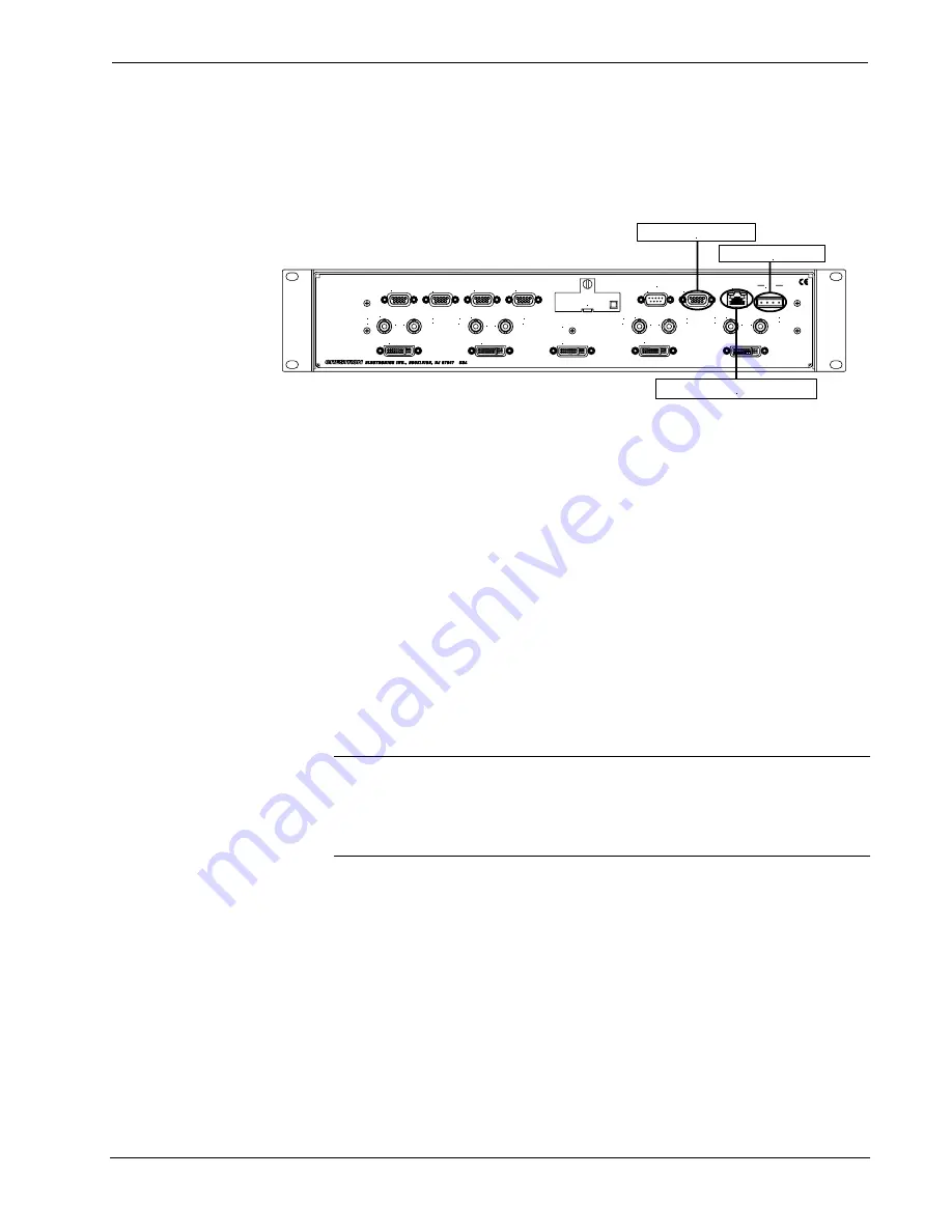
The following is for cable connections only. Refer to the following illustration for
typical connections.
Typical Connections for Programming
COM 1
COM 2
COM 3
COM 4
VIDEO INPUT 1
VIDEO INPUT 2
A
COMP
B
COMP
A
COMP
B
COMP
C
C
Y
Y
DVI/RGB
DVI/RGB
DVI/RGB
OUTPUT
A
COMP
B
COMP
VIDEO INPUT 3
VIDEO INPUT 4
C
Y
C
Y
A
C OMP
B
C OMP
DVI/RGB
DVI/RGB
TOUCHSCREEN
MOUSE
COMPUTER
LAN
NET
24 Y Z G
To PC (RS-232)
Cresnet Power
To Network (Ethernet)
MEMORY
EXPANSION
1. If not already connected, attach Cresnet cable to NET port and Cresnet
power. Ensure that 50 Watts of power is available.
2. If programming using RS-232, attach the RS-232 cable to the Computer
port and an available computer COM port of the PC. Refer to
“Communication Settings” on page 21.
3. If programming using Ethernet, attach the Ethernet cable to the LAN port
and the Ethernet port of the PC. Refer to Ethernet Setup on page 17.
Identity Code (Slave Mode on Cresnet)
All equipment and user interfaces within the network require a unique identity code
(NET ID). A two-digit hexadecimal number ranging from 03 to FE designates these
codes. The NET ID of each unit must match an ID code specified in the SIMPL
Windows program. The NET ID of the CNX-DVP4 has been factory set to
54
. The
NET IDs of multiple CNX-DVP4s in the same system must be unique and changed
from a PC via Viewport or from the setup menu of the CNX-DVP4, refer to page 24.
Complete the following procedure to change the NET ID.
NOTE:
If configured as a Cresnet Slave (ID 03 – FE) and as an Ethernet Slave with
“Set as Master” checked in the IP Table Entry, the Ethernet Slave takes priority.
NOTE:
For detailed information on establishing communication between the PC
and Control System, refer to the network’s Control System Operations Guide.
1. Ensure that the CNX-DVP4 is the only device connected (verify that the
software is running) to the control system.
2. Open
Viewport.
3. From the Viewport menu, select
Functions | Set Network ID
. The software
checks the baud rate and then opens the "Set Network ID" window.
4. In the "Set Network ID" window, select the CNX-DVP4 from the
Current
Network Devices
text window.
5. From
the
Choose the new network ID for the selected device (Hex):
text
box; select the new NET ID for the CNX-DVP4.
6. Click
Set ID
to initiate the change. This will display the "ID command has
been sent" window.
7. In the "Command Complete" window, click
OK
.
Operations Guide – DOC. 8170A
Digital Video Processor: CNX- DVP4
•
15


