background image

CNX Card Cage System                                                      Crestron 

CNRACKX

2  

••

  CNX Card Cage System: CNRACKX

Operations Guide - DOC. 8133

Physical Description

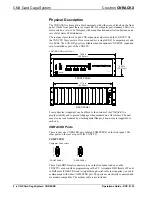
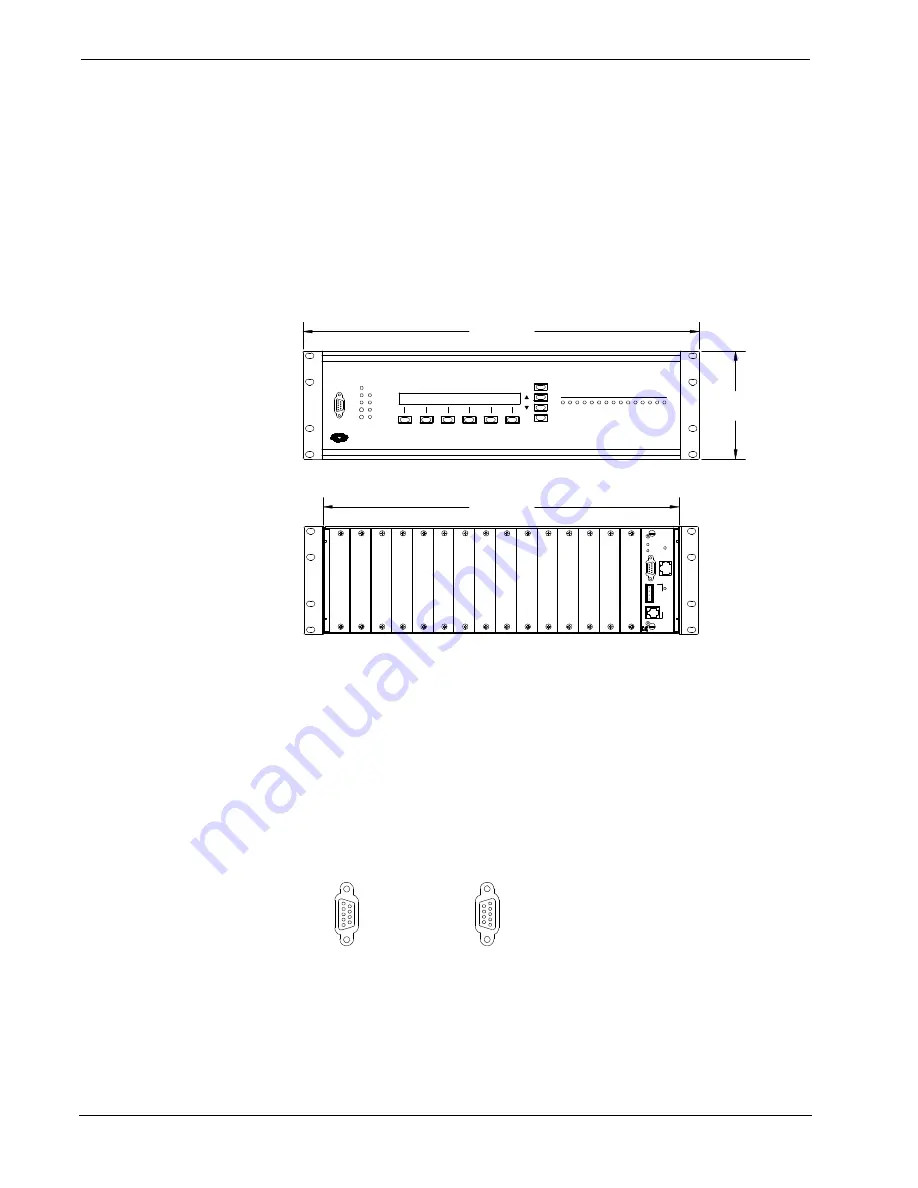
The CNRACKX is housed in a black enclosure with silk-screened labels on the front
panel. On the front panel there is a single RS-232 computer port, standard LEDs, two
reset buttons, a reverse LCD display with menu function and selection buttons, and a
row of slot status LED indicators.

The rear panel provides 15 open CNX expansion card slots and the CNXCPU. On
the CNXCPU, there are two Cresnet connectors, a single RS-232 computer port, and
two LEDs. The LAN/DPA port is available when the optional CNXENET expansion
card is installed as part of the CNXCPU.

CNRACKX Physical Views

5.20 in

(13.21 cm)

FRONT PANEL

REAR PANEL

17.16 in

(43.58 cm)

C
O
M
P
U
T
E
R

C
R
E
S
N
E
T

LAN

DPA

PROCESSOR

CONTROL

CNXCPU

G

Y

24

Z

COMPUTER

6

5

4

3

1

2

7

15

14

13

12

11

10

9

8

19.00 in

(48.26 cm)

CRESTRON

CRESTRON

P W R

P W R

NET

ERR

HW-R

SW-R

RXD

TXD

LNK

ERR

LAN

P R O F E S S I O N A L  C O N T R O L  P R O C E S S O R

I N T E R F A C E   C O N T R O L   C A R D   S L O T

M E N U

M E N U

BKLT

BKLT

CNRACKX

CRESTRON

PWR

NET

Four rubber feet (supplied) can be affixed to the bottom of the CNRACKX to
provide stability and to prevent slippage when mounted on a flat surface. The unit
may also be rack mounted by attaching metal flanges, known as ears (supplied), to
each end.

CNRACKX Ports

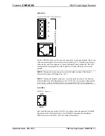
There is only one CNRACKX port, labeled COMPUTER, on the front panel. The
other ports on the rear are part of the CNXCPU:

COMPUTER

Computer Connectors

FRONT PANEL

REAR PANEL

C
O
M
P
U
T
E
R

COMPUTER

These 9-pin DB9 female connectors (one on the front panel and one on the
CNXCPU) are used when programming with a PC. A standard DB9 female (PC end)
to DB9 male (CNRACKX end) straight-through serial cable (not supplied) is used to
communicate with either COMPUTER port. The ports are electrically connected and
are modem compatible. The modem cable is not included.

Summary of Contents for CNRACKX

Page 1: ......

Page 2: ......

Page 3: ...r 10 Creating a Page with Front Panel Editor 11 Object Types 13 Loading Crestron Control Software 13 Installing Crestron Development Tools 13 Initial Setup 14 File Types 16 Obtaining Communications 18 Troubleshooting Communications 20 Loading the System Program 23 Testing the Permanent Memory Image 24 Loading Touchpanels 24 Updating the Control System 25 Problem Solving 28 Troubleshooting 28 Furth...

Page 4: ......

Page 5: ...rd cage slots accept any combination of CNX expansion cards A slot for the CNXCPU that optionally features Crestron s exclusive DPA Direct Processor Access port for Ethernet LAN expansion of the control network This port provides high speed access directly to the processor while maintaining bandwidth network connections The DPA permits 10BaseT and is ready to support Firewire ATM 100BaseT and othe...

Page 6: ... 15 14 13 12 11 10 9 8 19 00 in 48 26 cm CRESTRON CRESTRON P W R P W R NET ERR HW R SW R RXD TXD LNK ERR LAN P R O F E S S I O N A L C O N T R O L P R O C E S S O R INTERFACE CONTROL CARD SLOT MENU MENU BKLT BKLT CNRACKX CRESTRON PWR NET Four rubber feet supplied can be affixed to the bottom of the CNRACKX to provide stability and to prevent slippage when mounted on a flat surface The unit may als...

Page 7: ...ansion slot load The ports are wired in parallel NOTE If using the 4 wire connector review the latest revision of the Cresnet Network Interconnect Drawing Doc 5411 NOTE If using the modular connector review the latest revision of the Crestron Network Modular Cable Requirements Doc 5682 Most 6 conductor phone cables are wired in a crisscross fashion and are not compatible with Crestron equipment LA...

Page 8: ... press the MSG from the Default Info Menu and MENU DOWN buttons to examine the error s The LED extinguishes after the last message has been read NOTE The next four LEDs are active only if the optional CNXENET Expansion Card is installed and the CNRACKX is connected to a LAN RXD LAN This LED illuminates during reception of Ethernet data by the CPU slot TXD LAN This LED illuminates during transmissi...

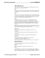
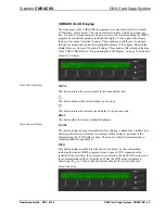
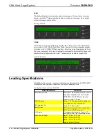
Page 9: ... Display Menu Selection Buttons MENU This button returns the screen display to the menu default state This button advances the screen display by one page This button returns the current screen display to its previous state BKLT This button alters the screen backlight brightness Menu Function Buttons PANEL This button displays a programmable interface offering command text indirect text and hierarc...

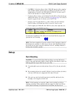
Page 10: ...u selection buttons respectively Default Time Menu Leading Specifications The tables below provide a summary of leading specifications for the CNRACKX Dimensions and weight are rounded to the nearest hundredth unit Leading Specifications of the CNRACKX SPECIFICATION DETAILS Power Requirements 24VDC from the CNPWS 75 External Power Supply not supplied Load Factor for the CNRACKX with CNXCPU only no...

Page 11: ...it has been tested and found to comply with specifications for CE marking NOTE This device complies with part 15 of the FCC rules Operation is subject to the following two conditions 1 these devices may not cause harmful interference and 2 these devices must accept any interference received including interference that may cause undesired operation Setup Rack Mounting WARNING To prevent bodily inju...

Page 12: ...section only applies to those applications using 4 wire Cresnet wiring When calculating the wire gauge for a particular network run the length of the run and the load factor of each network unit to be connected must be taken into consideration If network units are to be daisy chained on the run the load factor of each network unit to be daisy chained must be added together to determine the load fa...

Page 13: ...attaching power last complete the connections in any order The serial cable to the PC may be attached to the DB9 connector of the CNXCPU or to the DB9 connector on the CNRACKX front panel CAUTION To prevent overheating do not operate this product in an area that exceeds the recommended ambient temperature of 104 F 40 C Consideration must be given if installed in a closed or multi unit rack assembl...

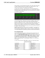
Page 14: ...e CNRACKX is preprogrammed with a certain level of diagnostic testing and network device information Assuming the CNRACKX is connected to a PC running SIMPL Windows a LCD display programming utility Front Panel Editor can be accessed This editor enables a programmer to program multi level pages under the PANEL left most function button on the LCD display Front Panel Editor The LCD display on a CNR...

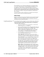
Page 15: ...en the Edit Panel Object dialog box This sample requires that headings be added to the page so choose Text Object from the Object Type area In the Inactive Text field enter Choose Device The object is displayed on the panel Click on and drag the object to its desired location on the panel top row Add additional objects VCR LaserDisc CD Lights and Volume to the page by double clicking in the displa...

Page 16: ...ed with digital channel 1 the VCR button is pressed the active text is displayed as a visual cue that the button is pressed Do the same procedure for each of the other function buttons in the Menu2 VCR Control page NOTE Digital channels are also referred to as join numbers Join numbers are numeric identifiers assigned to an object or button It is necessary to identify objects so the input output s...

Page 17: ...ial port of a PC If the PC has a DB25 male connector obtain a DB9 to DB25 adapter the adapter has a DB9 male end and a DB25 female end Installing Crestron Development Tools Crestron provides customers with software tools for programming the CNRACKX Even if only the control software is being loaded into the hardware and there are no plans to do any programming some Crestron development software mus...

Page 18: ... CRESTRON 2 Create a new folder for the project files Although the folder where the files are placed is not critical it is easier to manage projects if a logical structure is created For example create a new folder called PROJECTS underneath the CRESTRON directory Create another folder called MYJOB under PROJECTS for the current job The resulting pathname is C CRESTRON PROJECTS MYJOB 3 Copy the su...

Page 19: ...g Box The job may be copied to any folder or directory and the User IR Macro and SIMPL files will be copied to the proper directories If a version of SIMPL Windows lower than 1 30 01 is being used copy the ZIP file into the job directory stated in step 1 then extract the files with a program called WinZip Obtain a copy of this program from their website www winzip com on the internet Extract the f...

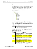
Page 20: ...ading the Control System Programs Subdirectory The files in this subdirectory contain the system program This is the main program that loads into the CNRACKX and determines the exact functionality of the system File Types in Programs Subdirectory FILE TYPE DESCRIPTION smw This is the SIMPL Windows program file It contains the source code for the main system program This file is required if changes...

Page 21: ...acro file It is needed during the convert compile process in order to properly compile the program To recompile the program use the Import Program option or copy any umc files umc received into the default user macro directory see SIMPL Windows help for more information Alternatively set the SIMPL Windows usermacro directory to the directory where the macros exist In SIMPL Windows this is accompli...

Page 22: ... connection sheets or other supplied information to determine which directory corresponds to a given touchpanel Obtaining Communications NOTE If the optional CNXENET Expansion Card is installed communications can be obtained with the CNRACKX over TCP IP The CNXENET Operations Installation Guide explains how to set up the control system for communications over Ethernet as well as communicating with...

Page 23: ... Viewport dialog box Accessing the Viewport 5 From the Setup menu verify that Auto Baud Search is checked Refer to illustration below Verifying Auto Baud Search 6 While the Viewport is displayed select Setup Communications alternatively depress Alt D to open the Port Settings dialog box and refer to the illustration below Accessing the Port Settings Dialog Box ...

Page 24: ...n alternatively depress F5 from the Viewport The viewport may display a window as it scans various baud rates Eventually a message should appear in the Incoming section showing a version number Such a response indicates that communications have been established If a No Communications with Rack error message appears proceed to Troubleshooting Communications below If the baud rate of the CNRACKX was...

Page 25: ...y that the proper COM port on the PC has been selected Some computers have more than one COM port some of which may be internal e g for a modem If verification can not be made consult the user s manual or contact the PC manufacturer 4 Check the NET and ERR LEDs on the front of the CNRACKX If either LED is illuminated unplug the unit and reapply power after a few seconds If either LED illuminates a...

Page 26: ...s not hooked up wait approximately three to four seconds Release the SW R button 5d If the CNRACKX responds proceed to step 5e Otherwise do the following Remove power from the CNRACKX Depress and hold the SW R button on the CNRACKX front panel Reapply power to the CNRACKX Wait until a message similar to the Viewport message above appears NOTE If a computer is not hooked up wait approximately three...

Page 27: ...ed contact Crestron technical support for assistance Refer to Further Inquiries on page 28 Loading the System Program To load the system program into the CNRACKX use the Crestron Viewport or the Transfer Program option in SIMPL Windows For consistency the steps that follow this paragraph use the viewport To upload a BIN file into the CNRACKX complete the following steps in the order provided 1 Sel...

Page 28: ...t Program field of the Cresnet Simpl Program dialog box should update and display the file currently loaded If the information does not update repeat steps 3 through 5 If this does not remedy the problem call Crestron technical support Refer to Further Inquiries on page 28 Testing the Permanent Memory Image To test the permanent memory image complete the following steps 1 Select Tools Viewport to ...

Page 29: ...that the panel displays a message saying that the upload is in progress Updating the Control System The CNRACKX contains an Operating System a Monitor ROM and with the optional CNXENET expansion card a TCP IP Stack Although each are separate components they are packaged together in a Control System Update File Control system update files have the extension UPZ It is often necessary to update a con...

Page 30: ... is not known use the Browse button to navigate to a list of available update files When browsing make sure to choose only update files that end with UPZ Update Control System Dialog Box 3 After a file is selected the Update Control System dialog as shown below will query the CNRACKX to determine what versions of the Operating system Monitor ROM and TCP IP Stack are currently running Example Updat...

Page 31: ...ot cause any problems Otherwise send all of the checked components To start the transfer click the Send button The transfer dialog will inform you of the progress in updating the selected components 5 As a result of the update a dialog box similar to below may appear and the SIMPL program and possibly SIMPL modules must be cleared Continue with transfer Selection Box 6 Upload the SIMPL program and...

Page 32: ... not illuminate SIMPL Windows program is not loaded properly Depress the SW R button to restart the SIMPL Windows program SIMPL Windows program error Verify the SIMPL Windows program Red ERR indicator illuminates Hardware or software failure hardware incom patibility with soft ware definitions or programming Verify that hardware configuration matches software configuration i e card is in proper sl...

Page 33: ...date of shipment to purchaser Disk drives and any other moving or rotating mechanical parts are covered for a period of one 1 year CRESTRON warrants all its other products for a period of one year from the defects mentioned above excluding touchscreen display components which are covered for 90 days Incandescent lamps are completely excluded from Crestron s Limited Warranty CRESTRON shall at its o...

Page 34: ......

Reviews: