

Crestron
CAT5 Wiring
Reference
Guide
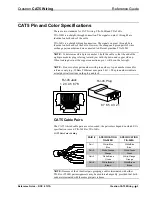
CAT5 Pin and Color Specifications
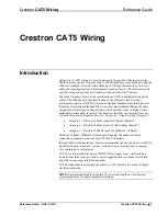
There are two standards for CAT5 wiring, TIA-568B and TIA-568A.
TIA-568B is a straight-through connection. The signals on pins 1 through 8 are
identical on both ends of the cable.
TIA-568A is a straight-through connection. The signals on pins 1 through 8 are
identical on both ends of the cable. However, the orange and green pairs of wires
exchange pair numbers and are connected to different pins than TIA-568B.
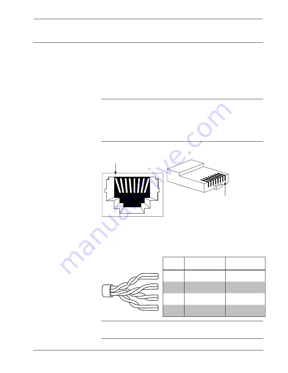
NOTE:
To determine which pin is number 1, hold the cable so that the end of the
eight pin modular plug is facing toward you, with clip down and copper side up.
When looking down at the copper connections, pin 1 will be on the far right.
NOTE:
Do not confuse pair numbers with pin numbers. A pair number is used for
reference only (e.g., 10BaseT Ethernet uses pairs 2 & 3). The pin numbers indicate
actual physical locations on the plug and jack.
1 2 3 4 5 6 7 8
RJ-45 Jack
8 7 6 5 4 3 2 1
RJ-45 Plug
CAT5 Cable Pairs
The CAT5 twisted cable pairs are color-coded; the pair colors depend on which EIA
specification is used, TIA-568B or TIA-568A.
CAT5 Pair Color Coding
PAIR #
SPECIFICATION
TIA-568B
SPECIFICATION
TIA-568A
White/Blue White/Blue
Pair 1
Blue Blue
White/Orange
White/Green
Pair 2
Orange
Green
White/Green White/Orange
Pair 3
Green Orange
White/Brown
White/Brown
Pair 4
Brown
Brown
NOTE:
Because of their identical pair groupings, cables terminated with either
T568A or T568B pair assignments may be used interchangeably, provided that both
ends are terminated with the same pin/pair scheme.
Reference Guide – DOC. 6137A
Crestron CAT5 Wiring
•
3


