


Crestron
CAT5 Wiring
Reference
Guide
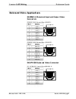
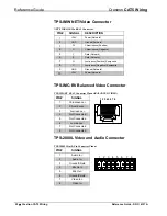
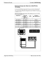
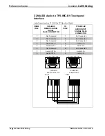
TPS-3000L/TPS-3100L/4000L NTSC/PAL Balanced
Video Input Connector
PIN #
SIGNAL
1
C (+) Chrominance
2
C (-) Chrominance
3
C (S) Chrominance Shield
4
Y (+) Luminance
5
Y (-) Luminance
6
Y (S) Luminance Shield
1 2 3 4 5 6
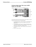
NOTE:
When sending balanced video from a CNX-BIPAD8 or CNX-PVID device,
only the positive and negative wires are connected to the touchpanel. Do not connect
the Shield (S) wires.
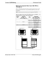
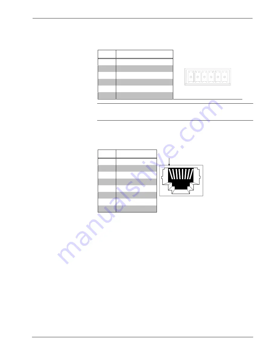
CNXRMC Balanced Video Input Connector
CNXRMC RJ-45 Connector Pinout (VIDEO IN)
PIN #
SIGNAL
1
Level 1 +
2
Level 1 -
3
Level 2 +
4
Level 3 +
5
Level 3 -
6
Level 2 -
7
Level 4 +
8
Level 4 -
1 2 3 4 5 6 7 8
Level 1 = Composite Video
Level 1 plus 2 = S-Video (Y on level 1 and C on level 2)
Level 1 plus 2 plus 3 = Component Video (Y, P
B
, P
R
)
Level 4 = Composite Video (fixed compensation) or Digital Audio
Reference Guide – DOC. 6137A
Crestron CAT5 Wiring
•
23


