21
SPEAKER CABLE CONNECTIONS
We recommend 18 AWG to 12 AWG speaker cable size for best performance.
speaker cable size for CRESCENDO EVOLUTION THREE 3A6 is 8 AWG.
REMOTE CABLE CONNECTIONS
Remote cable is not as important as other cable. But, choose a cable with good isolation to
prevent problem in the future. We should remember that car is always facing extreme hot
weather, cold weather, and vibration.
GAIN SENSITIVITY
Set the amplifier input sensitivity in accordance with the power output of head unit,
from 4 Volt to 200 mVolt. Gain position at is for head unit with high voltage output and
gain position at is for head unit with extremely small voltage output.
MONO / STEREO ADJUSTMENT
Mono and stereo configuration can be adjusted from the provided switch
mono mode will combine the left and right channels intended for using
configuration, while switch on the stereo mode will separate the left and rig
intended for using speakers in stereo configuration.
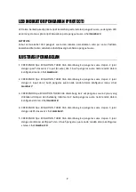
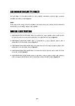
LED INDICATOR ON (POWER)
LED will light up when amplifier is working properly. Look at
Figure 5.
Figure 5
speaker cable size for best performance.
Maximum
Remote cable is not as important as other cable. But, choose a cable with good isolation to
uture. We should remember that car is always facing extreme hot
accordance with the power output of head unit, starting
is for head unit with high voltage output and
from the provided switch. Switch on the
for using speaker in mono
switch on the stereo mode will separate the left and right channels
Summary of Contents for EVOLUTION THREE 3A6
Page 1: ...0...
Page 4: ...3 KONEKSI KABEL POWER Gambar 2...
Page 5: ...4 KONEKSI KABEL POWER Gambar 3...
Page 6: ...5 KONEKSI KABEL POWER Gambar 4...
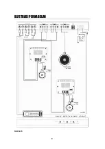
Page 9: ...8 ILUSTRASI PERKABELAN Gambar 6...
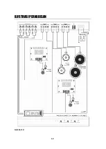
Page 10: ...9 ILUSTRASI PERKABELAN Gambar 7...
Page 11: ...10 ILUSTRASI PERKABELAN Gambar 8...
Page 12: ...11 ILUSTRASI PERKABELAN Gambar 9...
Page 13: ...12 ILUSTRASI PERKABELAN Gambar 10...
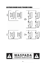
Page 14: ...13 ILUSTRASI KONEKSI KABEL PENGERAS SUARA...
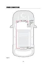
Page 19: ...18 POWER CONNECTIONS Figure 2...
Page 20: ...19 POWER CONNECTIONS Figure 3...
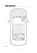
Page 21: ...20 POWER CONNECTIONS Figure 4...
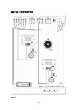
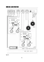
Page 24: ...23 WIRING ILLUSTRATION Figure 6...
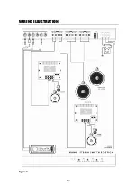
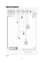
Page 25: ...24 WIRING ILLUSTRATION Figure 7...
Page 26: ...25 WIRING ILLUSTRATION Figure 8...
Page 27: ...26 WIRING ILLUSTRATION Figure 9...
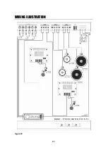
Page 28: ...27 WIRING ILLUSTRATION Figure 10...
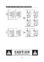
Page 29: ...28 SPEAKER WIRING CONNECTION ILLUSTRATION...
Page 32: ...31...

