- 2 -
A
A
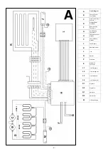
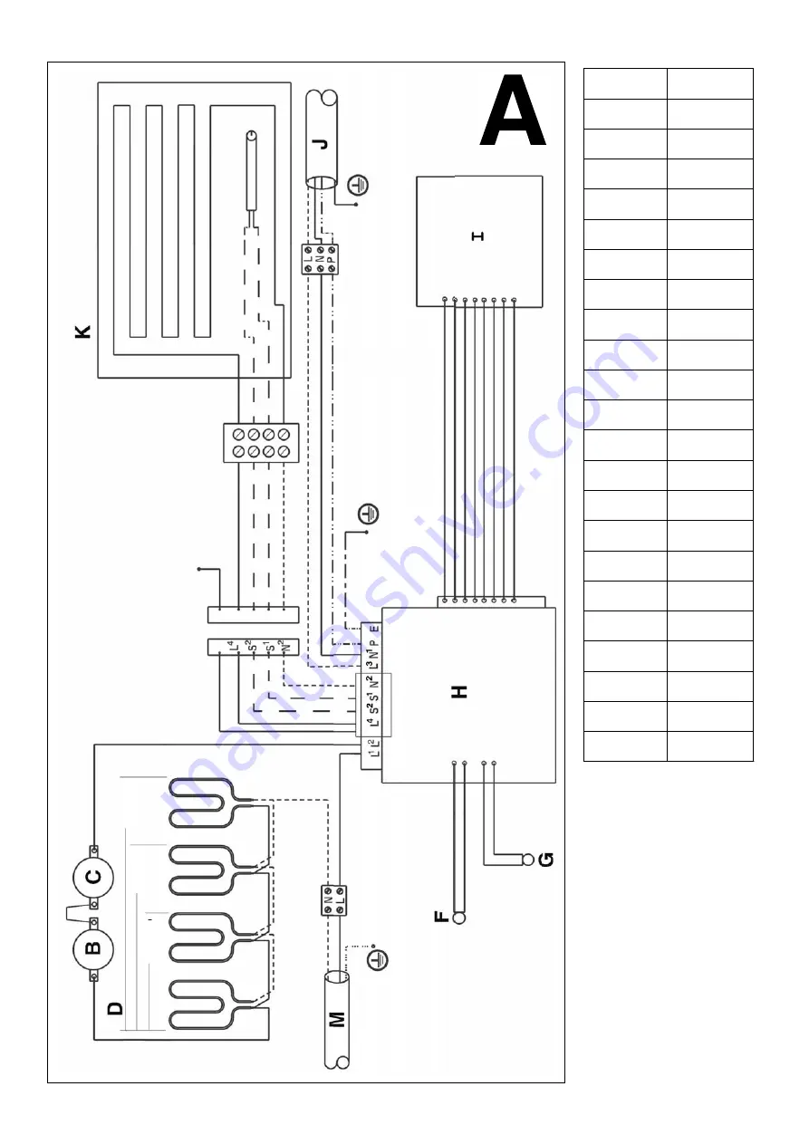
Circuit Diagram
B
Charge Control
Thermostat
C
Over Temperature
Cut Out
D
StorageHeater
Elements
F
Room Sensing
Thermistor
G
Core Sensing
Thermistor
H
Charge Controller
Module
I
User Interface
Module
J
Peak Supply
K
Radiant Element
L
Live
N
Neutral
P
Pilot Wire
E
Manual Fit
Connector
L1
Live Storage In
L2
Live Storage Out
L3
Live Radiant In
L4
Live Radiant Out
S1
Signal In
S2
Signal Out
N1
Neutral In
N2
Neutral Out
M
Off Peak Supply
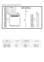
ER300
ER400
ER500


