background image

Catalog

Chapter 1 Summary

................................................................................................................................................

1

1.1 Equipment

...............................................................................................................................................

1

1.2 Features Characteristics

.......................................................................................................................

1

1.3 Specifications

..........................................................................................................................................

2

1.4 Controller Installation

.............................................................................................................................

3

1.5 System Connection Diagram

...............................................................................................................

4

Chapter 2 Hardware Description

...........................................................................................................................

5

2.1 CROSS-MAX0808 Panel View

............................................................................................................

5

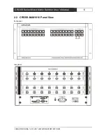
2.2 CROSS-MAX1616 Panel View

............................................................................................................

6

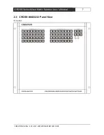
2.3 CROSS-MAX3232 Panel View

............................................................................................................

7

2.4 Matrix’s Connection with Peripherals

.................................................................................................

9

2.4.1 Input Interface Description

........................................................................................................

9

2.4.2 Output Interface Description

.....................................................................................................

9

2.4.3 Communication Port and Its Connection Method

.................................................................

9

2.4.4 Control Interface of Matrix RS-232

..........................................................................................

9

2.4.5 The Connection between Matrix and Control Computer

.....................................................

9

2.4.6 Matrix KEYBOARD Interface

....................................................................................................

9

2.4.7 The Connection between Matrix and Extended Keyboard

................................................

10

2.4.8 Matrix Network Interface

.........................................................................................................

10

2.4.9 The Connection Between Matrix and Computer Signal Input and Output Devices

......

11

2.4.10 DB15 Male Socket Transfer Line (S terminal, RCA head)

..............................................

12

2.4.11 PB-900 Power Supply Box

...................................................................................................

12

Chapter 3 Control Panel Operating Instructions

......................................................................................

14

3.1 Matrix Panel Description

.....................................................................................................................

14

3.2 Controller Panel Buttons Instructions

...............................................................................................

18

3.2.1 Switching Operation Example

................................................................................................

18

3.2.2 Save and Call Operation Example

........................................................................................

19

3.3 “Matrix Net Tool” Software Description

.............................................................................................

19

3.3.1 Software Running Environment

.............................................................................................

19

3.3.2 Software Startup

.......................................................................................................................

20

3.3.3 Open Program

...........................................................................................................................

20

3.3.4 The Main Interface

...................................................................................................................

20

3.4 Remote Control Description

...............................................................................................................

20

3.4.1 Functionality

..............................................................................................................................

20

3.4.2 System components

................................................................................................................

20

3.4.3 Connection Diagram

................................................................................................................

21

3.4.4 Instructions

................................................................................................................................

21

Chapter 4 Input, Output Card Instructions

........................................................................................................

23

4.1 Card Type

..............................................................................................................................................

23

4.2 Input Card

..............................................................................................................................................

23

4.2.1 Xin-HDMI8 Input Card Function Characteristics

.................................................................

23

4.2.2 Xin-DVI8 Input Card Function Characteristics

....................................................................

23

Summary of Contents for CROSS-MAX0808

Page 1: ...CROSS CROSS Series Series Mixed Mixed Matrix Matrix Switcher Switcher User User s s Manual Manual V1 0 Version CREATOR CORPORATION CHINA CREATOR CORPORATION CHINA ...

Page 2: ...t insulation occurring within the equipment may cause people suffer from shock CE certification means that the product has reached the directive safety requirements defined by the European Union Users can be assured about the use of it SGS certification means that the product has reached the quality inspection standards proposed by the world s largest SGS This product passed the ISO9001 internatio...

Page 3: ...ng Only after cutting down all external power source can install wiring operation begin or it may cause electric shock or equipment damage This product grounds by the grounding wires To avoid electric shocks grounding wires and the earth must be linked together Before the connection of input or output terminal please make sure this product is correctly grounded Immediately remove all other things ...

Page 4: ...ed parameters may be changed since the date of issue please inquire the supplemental information from CREATOR Electronics or local distributors The copyright of this manual belongs to CREATOR Electronics Without permission no unit or individual shall adopt part or all of its content for commercial use The manual is protected by of the Copyright Law of the Peoples Republic of China and other regula...

Page 5: ...terface 10 2 4 9 The Connection Between Matrix and Computer Signal Input and Output Devices 11 2 4 10 DB15 Male Socket Transfer Line S terminal RCA head 12 2 4 11 PB 900 Power Supply Box 12 Chapter 3 Control Panel Operating Instructions 14 3 1 Matrix Panel Description 14 3 2 Controller Panel Buttons Instructions 18 3 2 1 Switching Operation Example 18 3 2 2 Save and Call Operation Example 19 3 3 M...

Page 6: ...haracteristics 24 4 3 2 Xout DVI8 Output Card Function Characteristics 24 4 3 3 Xout CAT8 Output Card Function Characteristics 24 4 3 4 Xout SF8 Output Card Function Characteristics 24 4 4 Optional Accessories 24 4 4 1 FAN ASSEMBLY Function Characteristics 24 4 4 2 BC 100 Blank Card Function Characteristics 24 4 4 3 PB 900 Power Supply Box Function Characteristics 25 4 5 Specifications 25 Chapter ...

Page 7: ...tion the same or different types of input output cards can be consist of a single interface type or multi interface type matrix such as fiber matrix HDMI matrix DVI matrix CAT5 matrix VGA matrix YUV matrix S Video matrix Video matrix and so on CROSS series mixed matrix switcher has a variety of control modes supports crystal keys panel operation and RS 485 extended keyboard operation It provides t...

Page 8: ... convenient for users to work with a variety of remote control equipment Plug in card design flexible for configuration with different input and output signal type and signal channel number 1 3 Specifications Parameters Equipment Model 8 series 16 series 32 series Chassis height 3U 5U 10U Effective number of slots Input slot 1 2 4 Output slot 1 2 4 Input maximum signal road number Xin HDMI8 8 16 3...

Page 9: ...COM CROSS Series Mixed Matrix Switcher User s Manual 3 CROSS Series Mixed Matrix Switcher User s Manual 1 4 Controller Installation The matrix controller uses all metal box it can be mounted on a standard19inch cabinet steps are as follows ...

Page 10: ...CREATOR CHINA 2013 08 WWW CREATOR1997 COM CROSS Series Mixed Matrix Switcher User s Manual 4 CROSS Series Mixed Matrix Switcher User s Manual 1 5 System Connection Diagram ...

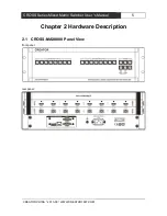
Page 11: ...NA 2013 08 WWW CREATOR1997 COM CROSS Series Mixed Matrix Switcher User s Manual 5 CROSS Series Mixed Matrix Switcher User s Manual Chapter 2 Hardware Description 2 1 CROSS MAX0808 Panel View front panel rear panel ...

Page 12: ...CREATOR CHINA 2013 08 WWW CREATOR1997 COM CROSS Series Mixed Matrix Switcher User s Manual 6 CROSS Series Mixed Matrix Switcher User s Manual 2 2 CROSS MAX1616 Panel View front panel rear panel ...

Page 13: ...CREATOR CHINA 2013 08 WWW CREATOR1997 COM CROSS Series Mixed Matrix Switcher User s Manual 7 CROSS Series Mixed Matrix Switcher User s Manual 2 3 CROSS MAX3232 Panel View front panel ...

Page 14: ...CREATOR CHINA 2013 08 WWW CREATOR1997 COM CROSS Series Mixed Matrix Switcher User s Manual 8 CROSS Series Mixed Matrix Switcher User s Manual rear panel ...

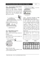
Page 15: ... RS 232 Digital seamless switching matrix provides 2 way RS 232 serial interface you can control the matrix through the interface The RS 232 port is a DB9 female connector Pins as follows Pin Signa l Description 1 2 TXD Used for RS 232 protocol send data 3 RXD Used for RS 232 protocol receive data 4 5 GND Signal ground 6 7 8 9 2 4 5 The Connection between Matrix and Control Computer Connecting the...

Page 16: ...ect connection method Matrix connects to an Ethernet switcher or hub via CAT 5 straight through cable 2 4 8 2 Connection Description of RJ45 Network Port Direct Line and Cross line The system adopts the CAT 5 super 5 cable as the wire Install RJ45 connector commonly known as crystal head at both ends of the CAT 5 to connect network devices The standard connection of twisted pair cable is not prede...

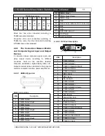
Page 17: ...al can be connected to the projector recorder computer monitors power amplifier etc 2 4 9 1 HDMI A Type Link HDMI A pinout table PIN Description 1 TMDS Data2 2 TMDS Data2 Shield 3 TMDS Data2 4 TMDS Data1 5 TMDS Data1 Shield 6 TMDS Data1 7 TMDS Data0 8 TMDS Data0 Shield 9 TMDS Data0 10 TMDS Clock 11 TMDS Clock Shield 12 TMDS Clock 13 CEC 14 Reserved in cable but N C on device 15 SCL 16 SDA 17 DDC C...

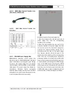
Page 18: ...veniently Methods to replace the power supply box 1 Open the screws at the left and right side of power supply box hold the corresponding handles pull it out slowly 2 Press the hook besides the wire pull off the connector inserted in the power supply box back one by one put on the new power supply box reconnect the related interface printing line in accordance with the note on the power supply box...

Page 19: ...CREATOR CHINA 2013 08 WWW CREATOR1997 COM CROSS Series Mixed Matrix Switcher User s Manual 13 CROSS Series Mixed Matrix Switcher User s Manual ...

Page 20: ...997 COM CROSS Series Mixed Matrix Switcher User s Manual 14 CROSS Series Mixed Matrix Switcher User s Manual Chapter 3 Control Panel Operating Instructions 3 1 Matrix Panel Description CROSS MAX0808 front panel CROSS MAX0808 rear panel ...

Page 21: ...CREATOR CHINA 2013 08 WWW CREATOR1997 COM CROSS Series Mixed Matrix Switcher User s Manual 15 CROSS Series Mixed Matrix Switcher User s Manual CROSS MAX1616 front panel CROSS MAX1616 rear panel ...

Page 22: ...CREATOR CHINA 2013 08 WWW CREATOR1997 COM CROSS Series Mixed Matrix Switcher User s Manual 16 CROSS Series Mixed Matrix Switcher User s Manual CROSS MAX3232 front panel ...

Page 23: ...orts on rear panel 2 OUTPUTS SELECTION Output channel selection key Signal output channel selection key is used to select output channel of mixed signals of audio and video infrared and serial corresponding to 8 16 32 output ports on rear panel 3 CONTROL Signal control area V RS For audio and video signals switcher with forward RS 232 and IR control signals VIDEO For separate switch of audio and v...

Page 24: ...dicates the connection is normal orange lights flashing suggests receiving or transmitting data 9 RS 232 RS 232 serial port 2 independent RS 232 ports can be used to connect PC or control equipment to realize the central control of system 10 Ground column 11 Power input port The system supports AC100 240V 50 60Hz input 3 2 Controller Panel Buttons Instructions Use the front panel buttons to quickl...

Page 25: ...ate here 3 2 2 Save and Call Operation Example Example synchronously input the audio and video and RS 232 and IR control signal of the current 1st channel the 3rd and 4th output channels are saved as No 6 and call The steps are as follows 1 Press the SAVE button the button lamp is lit 2 Press input channels key 6 key lamp is lit indicating the operation is successful the current input the output s...

Page 26: ... to communicate with matrix Can set network port IP address subnet mask gateway and MAC address of matrix through the main interface Current Settings reads the current network port parameters of the matrix Default Settings to restore the matrix network port parameters to the factory defaults The factory default value is as follows Port number 5000 IP address 192 168 0 2 Subnet Mask 255 255 255 0 G...

Page 27: ...r For the first time into the TP link setup interface it default display the status of the TP link information see Figure 2 4 below Remote control system TP link routers only do port mapping settings i e forwarding rules common routers have this feature Figure 2 4 B Select forwarding rules option on the left column of TP link setting page click on the virtual server and enter mapping settings page...

Page 28: ...matrix controller first you should know IP of public network connected by the matrix controller Only then can you start setting Set as follows The client PC run TCP UDP debugging software create a TCP Client connection fill in the IP address i e the IP of public network connected by the matrix controller port number i e the port number of matrix controller After the successful setting you can real...

Page 29: ...00 blank card Radiating card 4 2 Input Card 4 2 1 Xin HDMI8 Input Card Function Characteristics 8 HDMI A bus interface input The longest input distance is up to 20M Support EDID editing function Is compatible with the HDMI1 4 standard HDCP1 3 protocol DVI1 0 protocol Maximum support resolution HDPC 1920x1200P 60_24bit HDTV 1920x1080P 60_36bit 4 2 2 Xin DVI8 Input Card Function Characteristics 8 DV...

Page 30: ...gest input distance is up to 7M Is compatible with the HDMI1 4 standard HDCP1 3 protocol DVI1 0 protocol Maximum support resolution HDPC 1920x1200P 60_24bit HDTV 1920x1080P 60_36bit 4 3 2 Xout DVI8 Output Card Function Characteristics 8 DVI D female interface output The longest input distance is up to 7M Is compatible with the HDMI1 4 standard HDCP1 3 protocol DVI1 0 protocol Maximum support resol...

Page 31: ...odel Specifications Xin DVI8 DVI input card Xout DVI8 DVI input card Protocol Compatible with HDM11 3 standard HDCPl 3 protocol DVI l 0 protocol Video Gain 0 dB Pixel bandwidth 165MHz Full digital Interface bandwidth 2 25Gbps Full digital a total of 6 75Gbps each color is 2 25Gbps Maximum support resolution Normal PC 1600x1200P 60_24bit HDPC 1920x1200P 60_24bit HDTV 1920x1080P 60_36bit Clock Jitte...

Page 32: ...tput card Protocol Complete support for the HDMI1 4 protocol of 3D including support for the mainstream of 3D display mode in HDM11 4 protocol but does not include the 3D_1080P 120Hz downward compatible with HDM11 3 standard HDCPl 3 protocol DVIl 0 protocol Video Gain 0 dB Pixel bandwidth 165MHz Full digital Interface bandwidth 2 25Gbps Full digital a total of 6 75Gbps each color is 2 25Gbps Maxim...

Page 33: ... 1920x1080P 60_36bit 3D Format 1920x 1080P 24_36bit Signal type High speed differential signal defined in HDBaseT protocol Cable transmission power With PoE power supply 12V for CAT5 series transmitter of our company needing PoE power supply this card can provide it power via cable Note that this card cannot be connected to the transmitting device with PoE power With PoE power supply 12V for CAT5 ...

Page 34: ...igh speed single core SC optical fiber interface input Video Optical interface SC connector Fiber type Multimode Single Mode Optional Wavelength Multimode 850nm Single Mode 1310 1620nm Optional Interface bandwidth Positive 6 25Gbps reverse 3 125Gbps Clock Jitter 0 15Tbit Rise time 0 3Tbit 20 80 Fall time 0 3Tbit 20 80 The recommend ed maximum input output distance OM3 multimode optical fiber less ...

Page 35: ...al 2V 2V RGB signal 0V 1 0V HV signal 0V 5 0V Input impedance 75 Ω 75 Ω 75Ω 75Ω Echo loss 30dB 5MH z 30dB 5MHz 30dB 5MHz 30dB 5MHz Weight About 1 2KG Maximum power dissipation 50W Specifications Model CROSS MAX0808 CROSS MAX1616 CROSS MAX3232 Interface Input card number input channels 1 8 2 16 4 32 Output card number output channels 1 8 2 16 4 32 Input card model Xin DVI8 Xin HDMI8 Xin CAT8 Xin FB...

Page 36: ...control protocol TCP IP Ethernet Rate control Adaptive 10m 100m in full or half duplex Specifications Power supply 100VAC 240VAC 50 60 Hz The adaptive power supply Storage use temperature 20 70 C Storage use humidity 10 90 Dimension 3U 483mm L X354mm W X132 5mm H 5U 483mm L X354 mm W X221 5mm H 10U 483mm L X404mm W X443 6mm H Weight About 5 3KG without any card About 9 0KG without any card About 1...

Page 37: ...structions Computer to the matrix Command functions Return matrix to computer For example Establish a single connection X1 V Y1 Audio and video input X1 connected to audio and video output Y1 AV X1 Y1 1V1 X1 A Y1 Audio and video input X1 connected to audio and video output Y1 AV X1 Y1 1A1 X1 B Y1 Audio and video input X1 connected to audio and video output Y1 AV X1 Y1 1B1 RX1 R TY1 Serial receivin...

Page 38: ... Y1 Audio and video input X1 connected to audio and video output Y1 AV X1 Y1 1 1 X1 Y1 Audio and video input X1 connected to audio and video output Y1 AV X1 Y1 1 1 X1 Y1 Audio and video input X1 connected to audio and video output Y1 AV X1 Y1 1 1 X1 Y1 Audio and video input X1 connected to audio and video output Y1 AV X1 Y1 1 1 X1 Audio and video input X1 connected to audio and video output Y1 ser...

Page 39: ...iveing channel RX1 connected to the multi channel serial output port infrared transmitting channel TY1 TY2 TYn RS232 IR forward and reverse multi channel switching RS RX1 TY1 IR RX1 TY1 RS RX1 TY2 IR RX1 TY2 RS RX1 TYn IR RX1 TYn 1T1 2 3 X1 W Y1 Y2 Yn One way audio and video input X1 connected to the multi channel audio and video output Y1 Y2 Yn one way serial Input port infrared receiving channel...

Page 40: ...i channel audio and video output Y1 Y2 Yn multi channel serial input port infrared receiving channel RX1 RX2 RXn connected to the multi channel corresponding serial output port infrared transmitting channel TY1 TY2 TYn multi channel serial output port infrared receiving channel RY1 RY2 RYn connected to the multi channel corresponding serial input port infrared transmitting channel TX1 TX2 TXn X1 A...

Page 41: ... 0W Y1 Disconnect one way audio and video output Y1 and serial output port infrared transmitting channel TY1 B OFF Y1 RS OFF TY1 IR OFF TY1 0W1 0 R TX1 Disconnect one way serial input port TX1 RS OFF TX1 0 R1 0 Q TX1 Disconnect one way infrared transmitting channel output port TX1 IR OFF TX1 0 Q1 0 T TX1 Disconnect one way serial input port infrared transmitting channel TX1 RS OFF TX1 IR OFF TX1 0...

Page 42: ...ulti channel serial output port infrared transmitting channel TY1 TY2 TYn B OFF Y1 RS OFF TY1 IR OFF TY1 B OFF Y2 RS OFF TY2 IR OFF TY2 B OFF Yn RS OFF TYn IR OFF TYn 1 2 3W TX1 TX2 TXn R Disconnect multi channel serial transmitting channel input port TX1 TX2 TXn RS OFF TX1 RS OFF TX2 RS OFF TXn 1 2 3 R TX1 TX2 TXn Q Disconnect multi channel infrared transmitting channel input port TX1 TX2 TXn IR ...

Page 43: ...ction status of serial input port infrared receiving channel RX1 RX2 RXn and transmitting output channel TY1 TY2 TXn and serial output port infrared receiving channel RY1 RY2 RYn and transmitting input channel TX1 TX2 TXn inquire connection status of RS232 IR bidirectional channels RS RX1 TYn IR RX1 TYn RS RX2 TYn IR RX2 TYn RS RXn TYn IR RXn TYn RS RY1 TXn IR RY1 TXn RS RY2 TXn IR RY2 TXn RS RYn ...

Page 44: ...to computer For example Save N N 1 2 3 8 Save the connection state of all audio and video serial infrared to the N global setting Save To F N Save2 Recall N Recall from the N global pre set as the current connection state Recall From F N Recall2 Clear N Clear the N global default and its name Clear F N Clear2 Security Settings instructions ASCII Instructions Computer to the matrix Command function...

Page 45: ...ple X1 H Y1 Y2 Yn Audio and video input X1 prohibit to output from Y1 Y2 Yn channel AV X1 Y1 SetForbidOK AV X1 Y2 SetForbidOK AV X1 Yn SetForbidOK 1H1 2 3 X1 F Y1 Y2 Yn Audio and video input X1 prohibit to output from Y1 Y2 Yn channel AV X1 Y1 SetForbidOK AV X1 Y2 SetForbidOK AV X1 Yn SetForbidOK 1F1 2 3 QueryH X1 X 2 Xn Query the status that one way or multiplex audio and video cannot be output f...

Page 46: ...permissions restore to their default values hey can be put out from any output channel AllVEliminateForbidOK EliminateH All EliminateFAll All audio and video input channel permissions restore to their default values hey can be put out from any output channel AllAEliminateForbidOK EliminateFA ll Network Settings ASCII Instructions Computer to the matrix Command functions Return matrix to computer F...

Page 47: ...x IP SIPR X12 X13 X14 X15 SIPR SUBR Inquiry matrix subnet mask SUBR X12 X13 X14 X15 SUBR GAR Inquiry matrix gateway GAR X12 X13 X14 X15 GAR SHAR Inquiry matrix hardware address SHAR X12 X13 X14 X15 X16 X1 7 SHAR Common settings command ASCII Instructions Computer to the matrix Command functions Return matrix to computer For example Standardswitch Switch to standard mode STANDARDSWITCH Standardswit...

Page 48: ...t will automatically exit debugging mode without any operation in 10 minutes Note Only one input port can be activated during query output card debugging mode automatically exit after the use of the command and the port activated by input card debugging mode automatically become invalid Command OK 1 2 3 4SETI N Y1 Y2 Yn SETOUT Enter the output card debugging mode activate the port of COMP8 output ...

Page 49: ...ort resolution to 1400x1050 60Hz RESOLUTION 7 07C08 08C08 Set the active port resolution to 1440x900 60Hz RESOLUTION 8 08C08 09C08 Set the active port resolution to 1600x900 60Hz RESOLUTION 9 09C08 011C08 Set the active port resolution to 1680x1050 60Hz RESOLUTION 11 11C08 012C08 Set the active port resolution to 1920x1080 60Hz RESOLUTION 12 12C08 013C08 Set the active port resolution to custom re...

Page 50: ...y the current active port resolution RESOLUTION xx 06C30 09C30 Restore the current active port to factory settings Command OK 09C30 Network default parameters Matrix port 5000 Matrix IP 192 168 0 2 Matrix gateway 192 168 0 1 Matrix subnet mask 255 255 255 0 Matrix hardware address 0x00 0x11 0x22 0x33 0x44 0x55 Note The network parameters come into effect only after restarting the matrix system 1 R...

Page 51: ...CREATOR CORPORATION CHINA Copyright by CREATOR Last Revision 08 2013 ...

Reviews: