PSM6P
Powered Full Range Enclosures
5
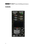
1. POWER LED:
This LED illuminates when the unit is on. The blue LED on
the front of the enclosure (not shown) also illuminates when the unit is on.
2. MIC/LINE:
Use this switch to set the input for the type of source connected
to the Input jack of the PSM6P. For microphones, set the switch to the Mic
position (switch depressed). For line level signals, such as the output of a
mixer, set the switch to the Line position (switch out).
3. GAIN:
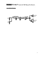
Use this control to adjust the level of the input signal when the
Mic/Line switch (#2) is in the Mic position (switch depressed).
4. TONE:
Use this control to adjust the equalization of input signal. Rotating
this control counter clockwise boosts the low frequencies, rotating this control
clockwise boosts the high frequencies.
5. VOLUME:
Use this control to adjust the speaker’s output level.
6. INPUT:
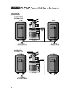
Use this jack to connect the signal source to the PSM6P - see
Applications on page 6.
7. AUX OUT:
Use this jack to connect the PSM6P to the Input jack of another
PSM6P when using multiple cabinets - see Applications on page 6. The output
of this jack is unaffected by the Gain, Tone, and Volume controls (#3, 4, 5).
8. VOLTAGE SELECTOR:
Use this switch to match the PSM6P to the AC line
voltage source.
9. FUSE:
The PSM6P uses a fuse to help protect the unit from damage due to
overload conditions. If the fuse fails replace it
only
with the same size and
type as indicated on the panel. If the fuse fails repeatedly, check the AC line
voltage source and the unit’s Voltage Selector switch (#8). If the problem per-
sists contact your Crate dealer.
10. POWER:
Use this switch to turn the PSM6P on and off. The Power LED (#1)
and the front panel blue LED illuminate when the power is on.
11. AC LINE CORD:
This grounded power cord is to be plugged into a
grounded power outlet, wired to current electric codes and compatible with
the voltage, power and frequency requirements stated on the rear panel.
Do
not attempt to defeat the safety ground connection.


