background image

4

REASSEMBLY

Reassembly will generally be in reverse order of 
disassembly. If disassembly was not complete, use only 
those steps related to your particular repair program.

1. 

The sleeve must be checked for abrasion, damage


during disassembly, or corrosion that can occur

 when 

fl uid residue penetrates between the seal (80)


and sleeve (14). The sleeve under the seal should


be lightly polished to a 32 RMS fi nish before 

 reassembly. 

Do not

 reuse a pitted or damaged 


sleeve. Slide the sleeve (14) on the motor shaft (6).

2. 

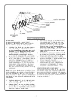
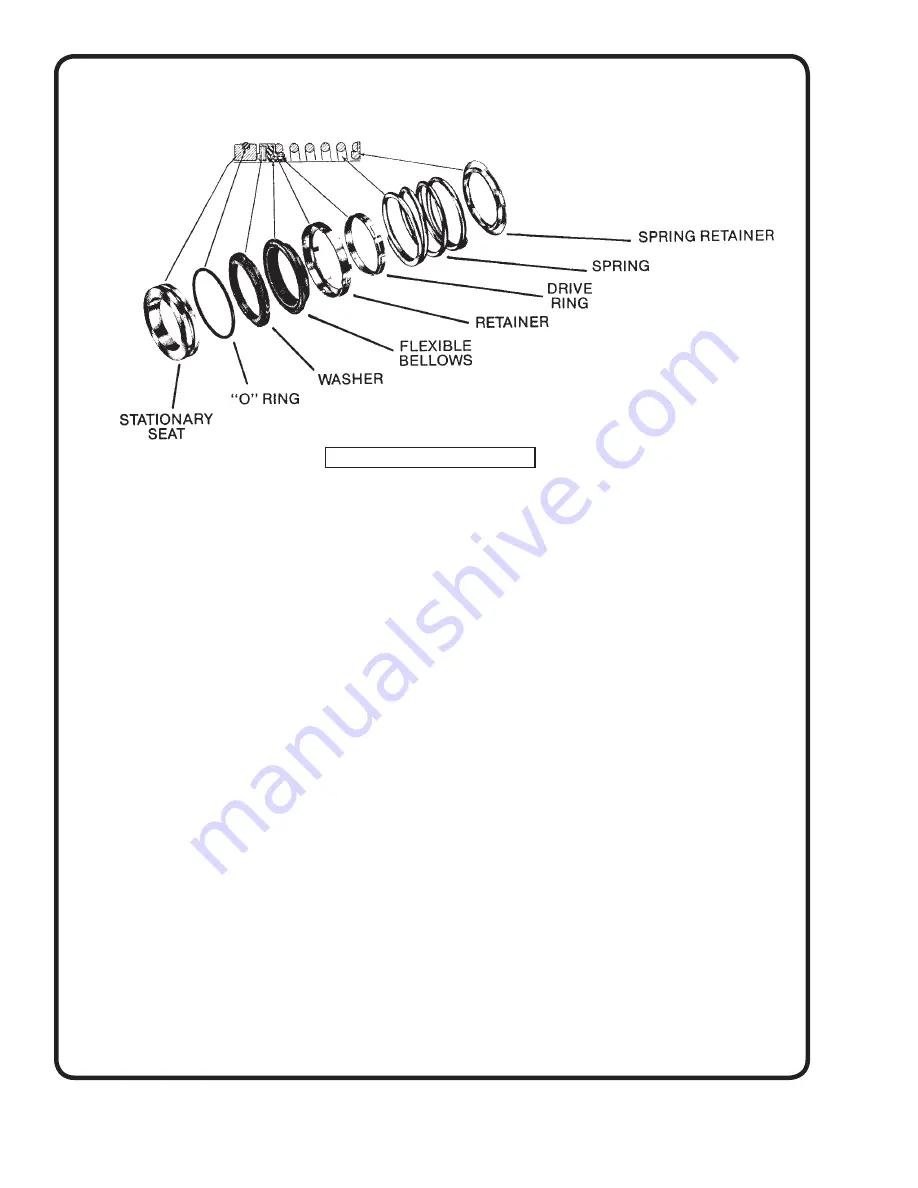
The mechanical seal (80) (See Figure 2) cannot be


installed as an assembly. It is necessary to have the


seal seat properly in place before the balance of 


parts can be added. Thoroughly inspect the seal 


cavity in the bracket for burrs or nicks which could


damage the seat of the seal. Apply a fi lm of soap

 paste 

or 

fl ax soap 

(Do not use oil or grease)

 to


the seal seat and install, taking care to seat it evenly

 and 

squarely.

NOTE:

 If it is not possible to insert seal with fi ngers, place 

cardboard protecting ring furnished with seal over lapped 
face of seat and press into place with a piece of tubing 
having end cut square. The tubing should be slightly larger 
than diameter of the shaft. Remove cardboard after seat is 
fi rmly in place.

3. 

Position casing cover (11) on the motor and secure


with capscrews (83). Tighten screws evenly to 


assure proper alignment.

4. 

Wipe the sealing faces of the seat and seal washer


clean. Oil these surfaces with a clean light oil. Lightly


oil the shaft sleeve (14). Slide the entire mechanical 


seal rotating assembly onto the sleeve.

5. 

Press wearing rings (25) and (27) into the casing 


(1) and casing cover (11). Rings should not be 


hammered into place. Use a press, or clamp the 


parts in a bench wise, using wooden blocks to 


protect the rings. It may be necessary to pin or 


dowel the rings after assembly if the insert or casing


has had rings replaced before, since each 


reassembly can stretch or tear metal and thereby

 loosen 

the 

fi ts.

6. 

Assemble key (32) and impeller (2) to motor shaft. 


Secure impeller (2) to motor shaft. Secure impeller 


(2) with washer (28) and impeller screw (26).

7. 

 Install all drain plugs in the casing. Position the 


gasket (73) and casing (1) against the casing cover 


(11) and secure with screws (82).

8. Repalce 

all 

fl ushing or drain lines. Connect 


discharge piping and suction piping if required, 


making sure to install gaskets on the fl anged 


connections. Connect electric power to motor.

STARTING PUMP AFTER REASSEMBLY

Do not pump until all air and vapor has been bled. Make 
sure that there is liquid in the pump to provide the neces-
sary lubrication, (Without the fl uid around it, the seal may 
be ruined in a few seconds of operation). It is possible that 
the mechanical seal may drip during the fi rst few minutes 
to one hour of operation.

Figure 2 - MECHANICAL SEAL

Summary of Contents for WEINMAN 6012CV

Page 1: ...37 773 7157 Fax 905 457 2650 www cranepumps com Form No 119978 Rev D TYPE CV Model 6012CV Size 6x6x12 WARNING DO NOT work on this pump until you are sure the pump and associated piping are totally depressurized and if pumping hot liquids that the temperature is safe to handle Be sure that electricity to the motor is shut off and locked out or if the motor is to be tested while running that it is c...

Page 2: ...discharge openings DO NOT insert fingers in pump with power connected Always wear eye protection when working on pumps Make sure lifting handles are securely fastened each time before lifting DO NOT operate pump without safety devices in place Always replace safety devices that have been removed during service or repair Secure the pump in its operating position so it can not tip over fall or slide...

Page 3: ...ped and therefore does not require additional lubrication The motor however may require lubrication in which case the motor manufacture s recommendation should be followed REPAIRS The pump may be disassembled using the illustrations and text provided Although complete disassembly is covered it will seldom be necessary to completely disassemble your Weinman In Line Unipump Inspect removed parts at ...

Page 4: ... with capscrews 83 Tighten screws evenly to assure proper alignment 4 Wipe the sealing faces of the seat and seal washer clean Oil these surfaces with a clean light oil Lightly oil the shaft sleeve 14 Slide the entire mechanical seal rotating assembly onto the sleeve 5 Press wearing rings 25 and 27 into the casing 1 and casing cover 11 Rings should not be hammered into place Use a press or clamp t...

Page 5: ...ient submergence for suction pipe 5 Excessive suction lift much over 15Ft 6 Insufficient positive suction head for hot water 7 Total head more than that for which pump is intended 8 Excessively worn impeller and wearing rings OVERLOADED DRIVING UNIT 1 Head much lower than that for which pump is designed 2 Speed too high Higher than that contemplated 3 Liquid handled of high specific gravity and gr...

Page 6: ...formance specifications must be in writing and such writing must be signed by our authorized representative Due to inaccuracies in field testing if a conflict arises between the results of field testing conducted by or for user and laboratory tests corrected for field performance the latter shall control RECOMMENDATIONS FOR SPECIAL APPLICATIONS OR THOSE RESULTING FROM SYSTEMS ANALYSES AND EVALUATI...

Page 7: ...nt To Insure That Employees Will Not Be Exposed To Health Hazards In Handling Said Material All Applicable Laws And Regulations Shall Apply IMPORTANT WARRANTY REGISTRATION Your product is covered by the enclosed Warranty To complete the Warranty Registration Form go to http www cranepumps com ProductRegistration If you have a claim under the provision of the warranty contact your local Crane Pumps...

Page 8: ...Notes ...

Reviews: