


8
MOISTURE SENSING RELAY
Moisture sensing replay is a conductance actuated control
for detecting moisture in the oil chamber of a submersible
motor. It is used as a warning device to indicate a
seal leakage and to signal the need for preventive
maintenance.
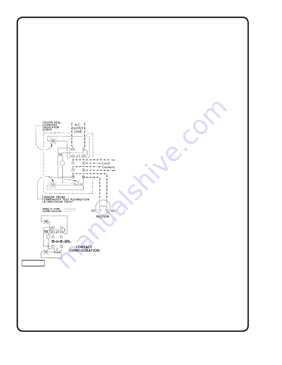
Mount the control box vertically on a wall or other solid
structure and complete all indicated wiring as shown
on the above wiring diagram. Terminals on the control
are numbered, as shown Terminal Pair I and 2 must be
continuously energized from an AC supply line of the correct
voltage as shown on the control data plate. Contacts 5 and
6 or 7 and 8 are available for connecting audible alarm
or light if required and must be wired in series with such
device; and that series branch circuit connected across the
power source compatible with the load. Terminals 9 and 10
are connected to the moisture sensing probe in the motors
marked WI and W2 by means of the cable provided with
the motor. See Figure 5.
OPERATION
Normally the oil surrounding the probes is non-conductive
and the control and seal leakage indicator light will be de-
energized. An infl ux of moisture past the outer seal and into
the oil reservoir will change the conductivity of the oil and
this condition will cause the relay to energize and the seal
leakage light and/or alarm will energize to indicate a seal
leakage. Load contacts 5 and 6 or 7 and 8 will also change
from their normally open position to a closed position when
the control energizes.
TEST PROCEDURES
A normally closed push-button and neon indicating
light are provided as a part of the control for testing the
moisture sensing components. The motor manufacturer
has provided a resistor across the probes inside the motor
to complete the test. When the test button is depressed
the neon indicating lamp and alarm if installed will be
activated to indicate:
A) Power is supplied to the control;
B) Control is operative;
C) The wiring to the moisture sensing probe in the
motor is intact.
This check does not stimulate a seal leakage, but indicates
that the circuit is operative should a leak occur.
Caution: The voltage will be present at all terminals on
the control when this test is being made.
LIQUID LEVEL CONTROL SYSTEM
A liquid level control system, to automatically start and
stop the pump(s), such as fl oat switch, mercury switches,
such as Deming Fig. 1601, or electrode probes with proper
relay must be installed with the pump. The actuating switch
for such controls is connected in the control circuit of the
magnetic starter.
Liquid level controls must be adjusted to stop the motor if
liquid level in the sump lowers to a point uncovering the
motor. If sump is to be drained—that is, motor uncovered—
some means, such as an automatic timing device, must
be used to limit uncovered operation to 10 minutes with
suffi cient time allowed for cooling of the motor before
restarting.
STARTING
On the initial start-up, the motor and pump must be
checked for proper rotation prior to fi nal installation. See
section on “Direction of Rotation”. The motor should under
no conditions be operated for any appreciable length of
time unless submerged in the liquid as indicated above.
OPERATION
After the pump is in position, discharge piping has been
completed and all electrical connections made, the unit
may be started as follow’s:
1.
Adjust liquid level controls. Make certain that the
controls will stop the pump when the liquid level
reaches the level shown on the Dimension Print on
Page 3. This minimum level is for continuous
operation and results in the motor being completely
submerged at all times.
2.
Open discharge valve, if used.
3.
Allow liquid to enter sump or pit.
4.
Energize motor, either by automatic control device or
manually.
5.
Check liquid level operation as described in Step #1.
Figure 5


