4
4. Build a dam around sub-base at least 2” high for
grouting in with thin cement and after cement has
hardened, tighten anchor bolts.
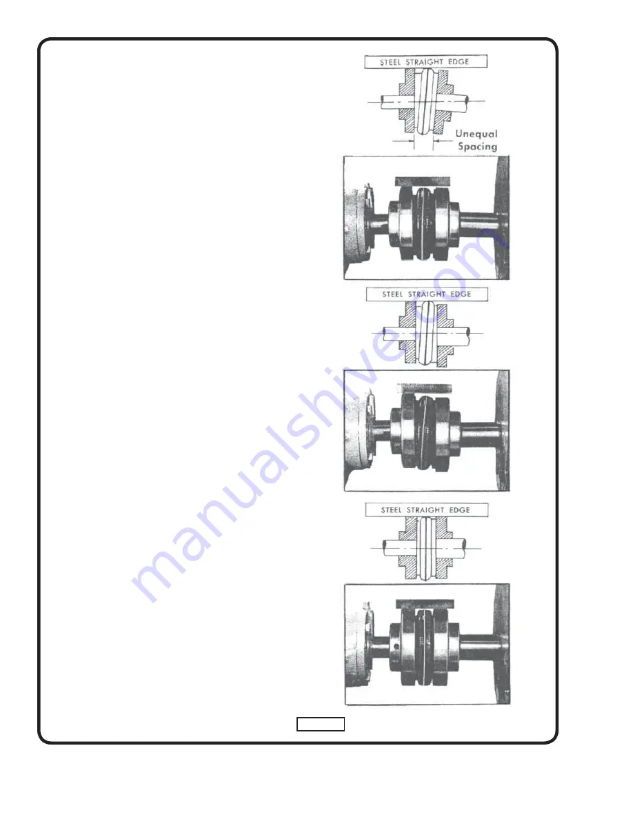
5. Recheck alignment at drive coupling. Any misalignment
now apparent should be corrected by metal shims
under pump or motor. When properly aligned, pump
shaft should turn freely by hand.
6. A foot valve and strainer must be installed on the lower
end of the suction pipe to keep pump completely
fi lled with liquid when the pump is used under suction
lift conditions. Connect suction pipe to pump casing.
When a foot valve is used, it is
absolutely necessary
to install a check valve
in the discharge line near the
pump to prevent possible broken casing due to line
shock or surge when the pump stops. A gate valve
should also be installed in the discharge line. Connect
discharge pipe to pump casing.
It is very important that the suction and discharge pipes
“line up” naturally with the pump. DO NOT “pull” pipes
into position with fl ange bolts. Support pipes
independently of the pump to eliminate all strain on
the pump casing. Select discharge pipe size so velocity
is under 8 feet per second. Avoid sharp changes in
pipe
sizes.
7. After pipes have been connected to pump, check
alignment at drive coupling. Correct any changes with
metal shims as in section “C”.
8. Check motor nameplate for electrical characteristics.
Be sure they are the same as the rating of the electrical
power available. Connect power lines to motor in accord
with wiring diagram on the motor and test motor
rotation, should turn in the direction indicated by arrow
cast on pump casing.
9. Fill pump (and suction pipe) with water. Close discharge
gate valve and start pump. When pump is up to speed,
slowly open the discharge valve to obtain desired
capacity and pressure.
D - LUBRICATION
The ball bearings (16) and (18) are double sealed and
lifetime lubricated by the manufacture before shipment.
Under normal operating conditions no further lubrication
is required. Any motor lubrication should be in accord with
motor manufacturer’s recommendations.
Figure 3
PERFECT
ALIGMENT
PARALLEL
MISALIGNMENT
ANGULAR
MISALIGNMENT
Summary of Contents for Deming 3904 Series
Page 10: ...Notes ...


