


Before proceeding remove all moisture from top cavity.
NOTE:
Excessive air pressure can cause leakage between seal seat
and rotating member. After air checking is complete remove
shaft seal retainer and install impeller.
Pump Cover Air Checking:
After cover assembly has been completed it is ready to be air
checked. Apply 10 to 12 PSI air pressure thru pipe plug (2) hole
in pump cover (1). Submerge unit in water. Any bubbling
indicates leakage and must be corrected. After it has been
concluded unit is not leaking apply pipe sealent to pipe plug (2)
and install in pump cover (1).
F-2 Assembly:
F-2.1Retaining Ring:
Install retaining ring (25) on shaft using care so shaft seal
mounting surfaces are not nicked or scratched.
F-2.2 Seal Seat:
Place drive end bell (29) with seal side up on end bell locating
tool (Fig 6) on arbor press. Apply small amount of light oil to
outside of Buna-N part of seal seat. Set squarely over seal seat
recess in end bell with ceramic side up. Using seal installation
tool (Fig. 7) and arbor press apply pressure until seat is
installed.
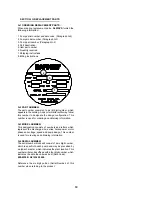
Fig. 5
TOOL USED FOR RETAINING SHAFT SEAL.
MATERIAL: 2.500" C.R.S. OR EQUIV.
Fig. 6
TOOL USED FOR LOCATING DRIVE END BELL.
MATERIAL: 2.50" DIA. C.R.S. OR EQUIV.
Fig. 7
TOOL USED FOR INSTALLATION OF SEAL SEAT.
MATERIAL: 1.125" DIA. ALUMINUM OR FIBER.
15
Summary of Contents for Barnes SPRINT II Series
Page 13: ...Fig 4 CONNECTION DIAGRAMS USED FOR DETERMINING WINDING RESISTANCE 13 ...
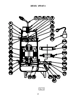
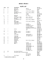
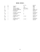
Page 21: ...Fig 15 SERIES SPRINT II 21 ...
Page 22: ...Fig 16 SERIES SPRINT II 22 ...
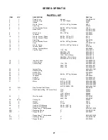
Page 25: ...SERIES SPRINT III Fig 17 25 ...
Page 26: ...SERIES SPRINT III Fig 18 26 ...
Page 28: ...NOTES 28 ...


