


SECTION E: PREVENTATIVE MAINTENANCE
As the motor is oil filled, no lubrication or other maintenance is
required, and generally Barnes pumps will give very reliable
service and can be expected to operate for years on normal
sewage pumping without failure. However, as with any
mechanical piece of equipment a preventive maintenance
program is recommended and suggested to include the
following checks:
1) Inspect motor chamber for oil level and contamination.
2) Inspect impeller and body for excessive build-up or
clogging.
3) Inspect seal for wear or leakage and repair as required
4) Clean sump or tank walls and floats where buildup of
debris could be harmful to pump operation.
5) Occasionally start pump manually to make certain it is
operational.
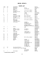
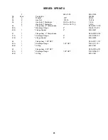
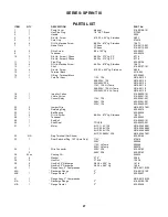
SECTION F: SERVICE AND REPAIR
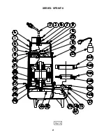
NOTE:
All item numbers ( ) refer to Figures 15 & 16, for SPRINT
II Series, 17 & 18 for SPRINT III series.
WARNING !
ELECTRICAL POWER TO THE PUMP MOTOR MUST BE
DISCONNECTED AND LOCKED OUT TO PREVENT ANY
DANGEROUS ELECTRICAL HAZARDS OR
PERSONNEL DANGER BEFORE ANY SERVICE WORK
IS DONE TO THE PUMP.
CAUTION:
OPERATING PUMP BUILDS UP HEAT AND PRESSURE;
ALLOW TIME FOR PUMP TO COOL TO ROOM
TEMPERATURE BEFORE HANDLING OR SERVICING.
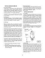
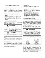
F-1) Lubrication:
Anytime the pump is removed from operation and at least every
twelve (12) months, the cooling oil in the motor housing (13)
must be checked visually for oil level and contamination.
F-1.1) Checking Oil:
To check oil, set unit upright. Remove screws (6) and pump
cover (1), then pipe plug (11). With a flashlight, visually inspect
the oil in the motor housing (14) to make sure it is clean, clear
and that the oil level is above all internal componentry. If oil
appears satisfactory, replace pipe plug. If oil is low or appears
contaminated, test oil as per section F-1.2
F-1.2) Testing Oil:
1.
Place pump on it’s side, remove pipe plug (11) and
drain oil into a clean, dry container.
2.
Check oil for contamination using an oil tester with a
range to 30 kilovolts breakdown.
3.
If oil is found to be clean and uncontaminated
(measures above 15 KV. breakdown), refill the motor
housing as per section F-1.3.
4.
If oil is found to be dirty or contaminated (or measures
below 15KV. breakdown), then the pump must be
carefully inspected for leaks at the shaft seal (30),
cord inlet (5), o-rings (9) & (28), and pipe plug (11)
before refilling with oil. To locate the leak, perform a
pressure test as per section F-1.4. After leak is repaired,
refill with new oil as per section F-1.3.
F-1.3 Replacing Oil in Motor Housing:
Drain all oil from motor housing and dispose of properly. Refill
with 52 ounces of new cooling oil as per Table 1. An air space
must remain in the top of the motor housing to compensate for
air expansion. Set unit upright and fill thru pipe plug (11). Oil
level should be at the top of the motor end bell. Oil level can be
checked by inserting a dipstick in pipe plug hole. Oil level should
be approx. .375" below top of surface.
After filling is completed insert pipe plug (11) and replace pump
cover (1), o-ring (9) and screws (6).
When refilling with oil after servicing the shaft seal (30), a
pressure test as per section F-1.4 should be done.
WARNING !
DO NOT OVERFILL OIL.
OVERFILLING OF MOTOR HOUSING WITH OIL CAN
CREATE EXCESSIVE AND DANGEROUS HYDRAULIC
PRESSURE WHICH CAN DESTROY THE PUMP AND
CREATE A HAZARD. OVERFILLING OIL VOIDS
WARRANTY.
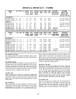
TABLE 1 - COOLING OIL - Dielectric
SUPPLIER
GRADE
BP
Enerpar SE100
Conoco
Pale Paraffin 22
Mobile
D.T.E. Oil Light
G & G Oil
Circulating 22
Imperial Oil
Voltesso-35
Shell Canada
Transformer-10
Texaco
Diala-Oil-AX
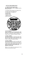
F-1.4) Pressure Test:
Motor Air Check -
After basic motor assembly is complete and
with seal retaining tool (Fig. 5) installed, motor is ready to be
air checked (impeller can be used in place of seal retaining tool
but it will be difficult to see where leakage, if present, is
occurring in seal area). Apply 6 to 8 PSI air pressure thru pipe
plug (11) hole in top of shell and submerge unit in water. Any
bubbling indicates leakage and must be corrected.
14
Summary of Contents for Barnes SPRINT II Series
Page 13: ...Fig 4 CONNECTION DIAGRAMS USED FOR DETERMINING WINDING RESISTANCE 13 ...
Page 21: ...Fig 15 SERIES SPRINT II 21 ...
Page 22: ...Fig 16 SERIES SPRINT II 22 ...
Page 25: ...SERIES SPRINT III Fig 17 25 ...
Page 26: ...SERIES SPRINT III Fig 18 26 ...
Page 28: ...NOTES 28 ...