
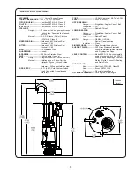
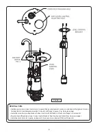
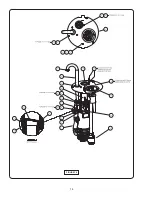


15
ITEM
QTY
PART NO.
DESCRITION
1
1
120300
Pump, OGP2022CO
2
1
121676NCE Switch. ESPS-150, No-Brkt
Not
Shown
1
113315
113315XC
Cord Set, 15Ft for ESPS
Cord Set, 30Ft For ESPS
3
3
625-03268
Stud, 5/16-18 x 1.50” Lg
4
3
118889
Rod, Support, Mount, Pump
5 †
1
625-01556
O-ring, -228
6 †
1
118252
Gasket, Assy, Flapcheck
7 †
1
118251
Seat, Valve, Flapper
8 †
2
112725
Pin, .125 x .75
9 †
13
1-156-1
Screw, HxHd, 5/16-18 x 1.00” Lg
10
13
026322
Washer, Lock, 5/16
11 †
1
118794
Housing, Valve, Body
12
1
625-01558
O-ring, -223
13
1
118956
Grommet, Black, Nitrile
14
1
118344
Fitting, Elbow,, E-one, 1.25”
15
1
118339
Grommet, Valve-Receiver
16
1
119037
Grommet, Black, Nitrile
17
2
085666
Eye Bolt, 3/16 x 1.00”
18
18A
2
Optional
093973
099286
Rope, 1/2” Dia x 120” Lg
Rope, 1/2” Dia x 204” Lg
19
3
118954
Clip, Retaining
20
1
118891
Support Bracket, ESPS Switch
22
1
118817
Plate, Support, Mount, Plate
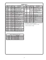
ITEM
QTY
PART NO.
DESCRITION
23*
1
115664
Rope, 1/4” x 15Ft.
1
111912
Cord Grip, .75”, .250-.375”
25
○
1
113291B
Circuit Breaker, 20 AMP,
GE THQP Snap in Breaker
105476
Circuit Breaker, 20 AMP,
DIN Rail Breaker
29†
1
See
Chart
Cord Set 12/5, Pump Power
33
2
15-23-1
Hex Nut, 3/8-16
34
2
082727
Flat Washer, 3/8”
35
5
055844
Connector Wire (Not Shown)
1
069054V
Cord Grip
37
5
2-12008-1
Zip Ties
38
1
119880
Pump Manual
39
1
105714
Plug
40
(*) Included with Level Control Switch Item 2.
(†) Included with pump when ordering part no. 120300
(
○
) Ordered separately see catalog
PARTS LIST
Item 29 - 12/5 Pump Power Cord
Part No.
Description
113274
15’ - 12/5 SOW, No EQD
113274XC
30’ - 12/5 SOW, No EQD
131960
15’ - 12/5 SOW with EQD
131960XC
30’ - 12/5 SOW with EQD
Summary of Contents for Barnes PS Omni Grind Plus OGP2022CO Series
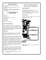
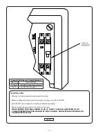
Page 11: ...11 FIGURE 8 ...
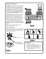
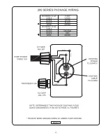
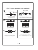
Page 12: ...12 FIGURE 9 Wiring for units not supplied with Factory Installed EQD ...
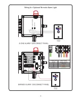
Page 13: ...13 Wiring for Optional Remote Alarm Light ...
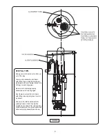
Page 14: ...14 FIGURE 10 ...
Page 16: ...Notes ...


