11
Place all motor leads above motor. Position square ring (42)
on seal plate (25) and lower motor housing (2) over motor
and into pilot. Place socket head cap screws (39) through
seal plate (25) into motor housing (2) and torque to 75
inch pounds. Make wire connections per paragraph F-3.3.
Assemble impeller and volute per paragraph F-2.2.
F-3.3) Wiring Connections:
Check power cords (10) for cracks or damage and replace
if required. Make internal wiring connections which are
independent of the terminal block as shown in (Figure 10),
using connectors (23) and wire assemblies (29) as required.
Do not use wire nuts. Slip motor leads and ground wire
through fi berglass sleeve (22). Lower motor housing (2)
down onto seal plate (25) while aligning holes and stringing
motor leads through the cord entry bore(s). (Slipping cords
inside a 1 ft. length of .5” conduit makes this easier). Place
socket head cap screws (39) through seal plate (25) into
motor housing (2) and torque to 75 in-lbs.
Reconnect motor leads to the underside of the terminal
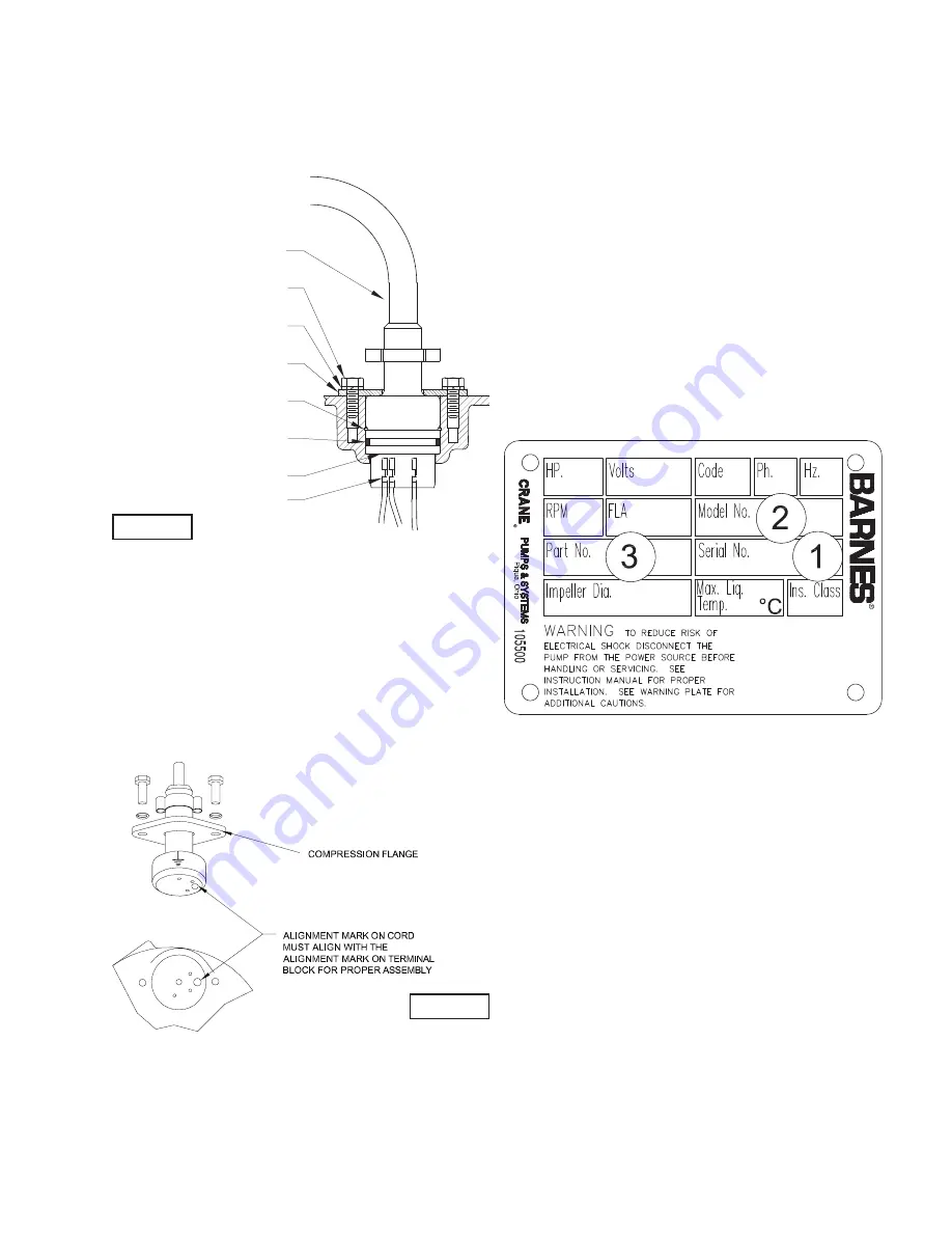
block(s) (27) as shown in Figure 8. Note that the pins are
numbered underneath the terminal block. Place o-ring (12)
into groove in terminal block (27) and lubricate with dielectric
oil. Press the terminal block (27) into the housing so it seats
completely below the snap ring groove. Place snap ring (8)
into groove in cord entry bore of motor housing (2). Repeat
terminal block installation for sensor cord, if equipped.
F-3.4) Cord Assemblies:
Power -
Refi ll the cooling oil as outlined in paragraph F-1.4.
Make wire connections as outlined in paragraph F-3.3.
Insert female end of cord plug into housing bore aligning
timing mark with hole in terminal block (27) (see Figure
5). Compress cord plug with compression fl ange (10a)
by tightening cap screws (24) into the motor housing (2).
Torque to 132 in-lbs.
SECTION: G REPLACEMENT PARTS
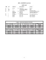
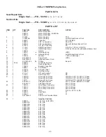
G-1 ORDERING REPLACEMENT PARTS:
When ordering replacement parts, ALWAYS furnish the
following information:
1. Pump serial number and date code. (Paragraph G-4)
2. Pump model number. (Paragraph G-3)
3. Pump part number. (Paragraph G-2)
4. Part description.
5. Item part number.
6. Quantity required.
7. Shipping instructions.
8. Billing Instructions.
G-2 PART NUMBER:
The part number consists of a six (6) digit number, which
appears in the catalog. A one or two letter suffi x may follow
this number to designate the design confi guration. This
number is used for ordering and obtaining information.
G-3 MODEL NUMBER:
This designation consists of numbers and letters which
represent the discharge size, series, horsepower, motor
phase and voltage, speed and pump design. This number is
used for ordering and obtaining information.
G-4 SERIAL NUMBER:
The serial number block will consist of a six digit number,
which is specifi c to each pump and may be preceded by
a alpha character, which indicates the plant location. This
number will also be suffi xed with a four digit number, which
indicates the date the unit was built (Date Code). EXAMPLE:
A012345 0490.
Reference the six digit portion (Serial Number) of this number
when referring to the product.
FIGURE 8
POWER CORD (10)
CAP SCREW (6)
Lock washer (4)
COMPRESSION FLANGE (10a)
SNAP RING (8)
O-RING (12)
TERMINAL BLOCK (27)
TERMINAL
FIGURE 9
Summary of Contents for Barnes 3SE3024L
Page 12: ...12 FIGURE 10 ...
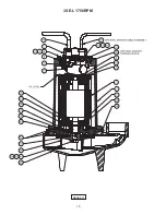
Page 14: ...14 FIGURE 11 3SE L 3450RPM ...
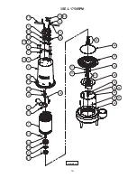
Page 18: ...18 3SE L 1750RPM FIGURE 13 ...
Page 24: ...24 Notes ...


