background image

6

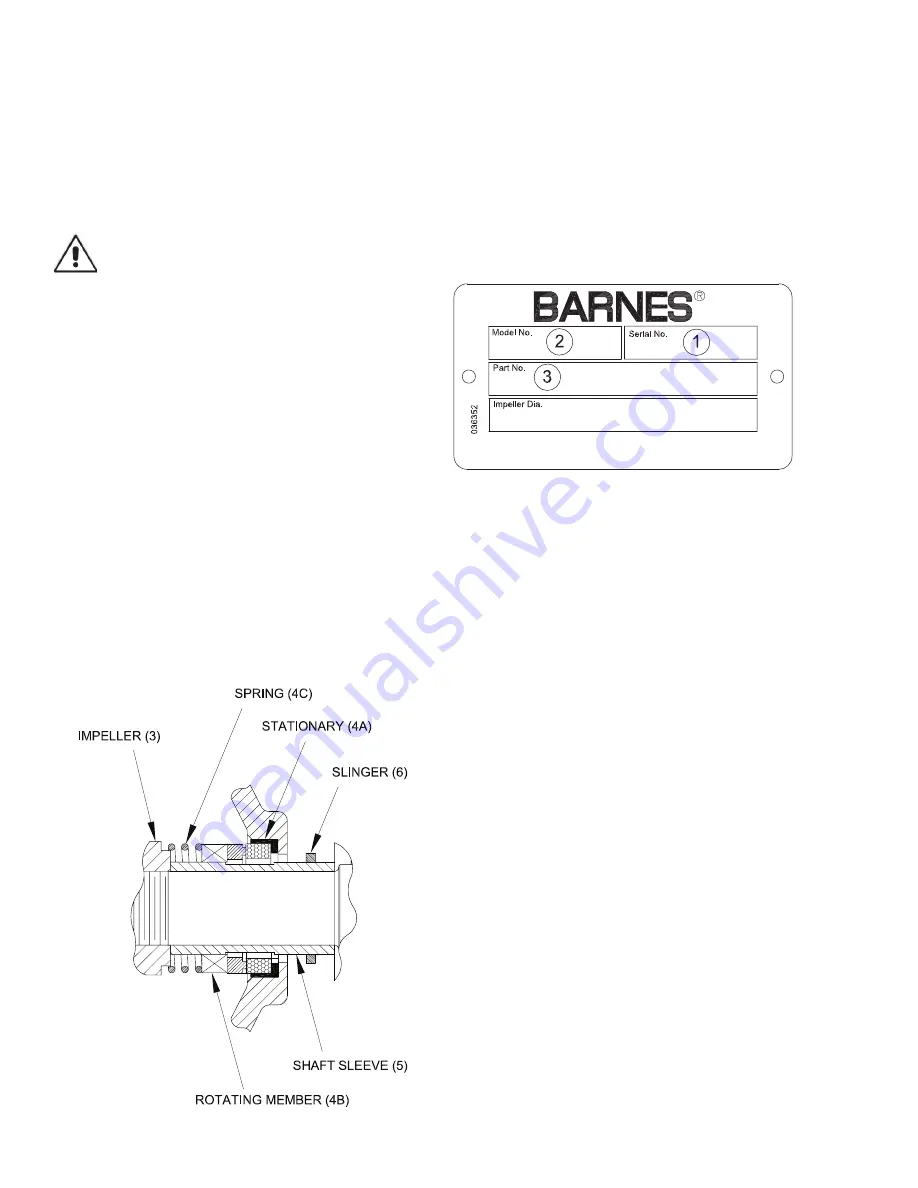
E-2) Shaft Seal Service:

To expose the seal for examination or replacement, remove 
volute and impeller as outlined in Section E-1. Remove 
spring (4C) and rotating member (4B) from shaft sleeve (5). 
All of the components of the shaft seal are now exposed for 
examination or repair. If any part of the shaft seal shows wear 
or damage, replace entire seal assembly.

When stationary member (4A) needs replaced, press used 
stationary member (4A) from pedestal (8).

CAUTION! - Handle seal parts with extreme care. 
DO NOT scratch or mar lapped faces.

Lightly oil and replace shaft sleeve (5) and stationary member 
(4A), press stationary member (4A) over shaft sleeve and 
into pedestal (8). Lightly oil shaft sleeve and inner surface of 
bellows of rotating member (4B). With lapped surface facing 
pedestal, slide rotating member (4B) onto shaft sleeve until 

lapped faces of (4A) and (4B) are together. If fi nger pressure 
is not suffi cient, use a piece of tubing making sure to press 
ONLY on bellows tail section not on metal retainer. Make 
sure driving lugs in retainer are mated in carbon washer. 
Place spring (4C) on shaft sleeve and in place on rotating 
member (4B) making sure it is seated on metal retainer and 
not cocked or resting on bellows tail. Reassemble remainder 
of pump.

E-3) Shaft and Bearing Service:

Remove volute, impeller and shaft seal as outlined in 
Sections E-1 and E-2. Remove cap screw (19), and 
lockwashers (18), and pull bearing cap (17) from pedestal 
(8). Tap on drive end of shaft (13) with a block of wood and a 
hammer to drive the shaft (13) and bearings (15) and (9) from 
pedestal (8). Examine all parts and replace those showing 
wear and/or damage. If bearings need repacked use a grease
such as SOHIO FACTRAN EP-3, or equal. Reassemble 
remainder of pump.

SECTION: F REPLACEMENT PARTS

F-1 ORDERING REPLACEMENT PARTS:

When ordering replacement parts, ALWAYS furnish the 
following information:

1. Pump serial number and date code. (F-4)
2. Pump model number. (F-3)
3. Pump part number. (F-2)
4. Part description.
5. Item part number.
6. Quantity required.
7. Shipping instructions.
8. Billing instructions.

F-2 PART NUMBER:

The part number consists of a six (6) digit number, which 
appears in the catalog. A one or two letter suffi x may follow 
this number to designate the design confi guration. This 
number is used for ordering and obtaining information.

F-3 MODEL NUMBER:

This designation consists of numbers and letters which 
represent the discharge size, series horsepower, motor phase 
and voltage, speed and pump design. This number is used 
for ordering and obtaining information.

F-4 SERIAL NUMBER:

The serial number block will consist of a six digit number, 
which is specifi c to each pump and may be preceded by 
a alpha character, which indicates the plant location. This 
number will also be suffi xed with a four digit number, which 
indicates the date the unit was built (Date Code). 

EXAMPLE: A012345 0490.

Reference the six digit portion (Serial Number) of this number 
when referring to the product.

Summary of Contents for 029676

Page 1: ...stems Inc constant product improvement program product changes may occur As such Crane Pumps Systems reserves the right to change product without prior written notification 420 Third Street 83 West Drive Bramton Piqua Ohio 45356 Ontario Canada L6T 2J6 Phone 937 778 8947 Phone 905 457 6223 Fax 937 773 7157 Fax 905 457 2650 www cranepumps com Form No 030174 Rev L Model 2020HCU Manual Index ...

Page 2: ...PARTS 6 TROUBLE SHOOTING 7 CROSS SECTION PARTS LIST 8 EXPLODED VIEW 9 RETURNED GOODS POLICY 9 WARRANTY 10 START UP REPORT 11 14 WARRANTY REGISTRATION Other brand and product names are trademarks or registered trademarks of their respective holders Barnes is a registered trademark of Crane Pumps Systems Inc 1984 2002 10 04 4 06 8 06 Alteration Rights Reserved ...

Page 3: ...de DO NOT exceed manufacturers recommendation for maximum performance as this could cause the motor to overheat When towing pump behind a vehicle make sure hitch is properly attached always attach safety chains WARNING If Engine driven never operate in an enclosed building or area where exhaust gases can accumulate Never operate near a building where exhaust gases can seep inside Never operate in ...

Page 4: ...ion Self Lubrication Material Rotating Faces Carbon Stationary Faces Ni Resist Elastomer Buna N Hardware 300 series stainless steel BEARING PUMP END Design Single Row Ball Lubrication Grease Factory Lubrication Load Radial Thrust BEARING DRIVE END Design Single Row Ball Lubrication Grease Factory Lubrication Load Radial Thrust OPTIONAL EQUIPMENT Discharge Check Valve Hand Primer Base OSHA Coupling...

Page 5: ... suction pipe or hose to suction inlet If hose is used it should be of the reinforced type to prevent collapsing under suction Make sure all suction system connections are tight and free of air leaks as even a very slight leak will greatly reduce priming ability and pumping efficiency CAUTION This pump should not be operated without a strainer on the end of the suction line to prevent sticks stones...

Page 6: ...9 and lockwashers 18 and pull bearing cap 17 from pedestal 8 Tap on drive end of shaft 13 with a block of wood and a hammer to drive the shaft 13 and bearings 15 and 9 from pedestal 8 Examine all parts and replace those showing wear and or damage If bearings need repacked use a grease such as SOHIO FACTRAN EP 3 or equal Reassemble remainder of pump SECTION F REPLACEMENT PARTS F 1 ORDERING REPLACEM...

Page 7: ...uction head higher than pump designed for 4 Insufficient inlet pressure or suction head 5 Clogged foot valve strainer or pump 6 Defective wearplate s 1 Repair or replace suction line 2 Refill reprime pump casing before restarting 3 Lower suction head install foot valve and primer 4 Increase inlet pressure by adding more water to tank or increasing back pressure by turning gate valve on discharge lin...

Page 8: ...163 Slinger 7 1 021297 Square Ring 8 1 029084 Pedestal 9 1 019846 Bearing 10 8 002410 Stud 5 16 18 x 1 75 Lg 11 8 002603 Lockwasher 5 16 12 8 002501 Hex nut 5 16 18 13 1 021038 Shaft 14 1 021092 Shaft Key 15 1 019847 Bearing 16 1 019851 Snap Ring 17 1 019845 Bearing Cap 18 3 002618 Lockwasher 10 19 3 019842 Machine Screw 10 32 x 50 Lg ZP 20 3 015000 Pipe Plug 375 NPT 21 2 003217 Pipe Plug 25 NPT 2...

Page 9: ...9 ...

Page 10: ...performance specifications must be in writing and such writing must be signed by our authorized representative Due to inaccuracies in field testing if a conflict arises between the results of field testing conducted by or for user and laboratory tests corrected for field performance the latter shall control RECOMMENDATIONS FOR SPECIAL APPLICATIONS OR THOSE RESULTING FROM SYSTEMS ANALYSES AND EVALUATION...

Page 11: ...ent To Insure That Employees Will Not Be Exposed To Health Hazards In Handling Said Material All Applicable Laws And Regulations Shall Apply IMPORTANT WARRANTY REGISTRATION Your product is covered by the enclosed Warranty To complete the Warranty Registration Form go to http www cranepumps com ProductRegistration If you have a claim under the provision of the warranty contact your local Crane Pump...

Page 12: ...Notes ...

Reviews: