background image

18

ASSEMBLY

Auger Control

 WARNING

Prior to operating your snow blower, carefully read and follow all 
instructions below. Perform all adjustments to verify your snow blower is 
operating safely and properly.

Check the adjustment of the auger control as follows:
1. 

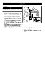
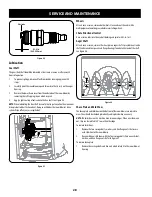
The auger control is located on the left handle. See Figure 37 inset. When 
the auger control is released and in the disengaged “UP” position, the cable 
should have very little slack. It should NOT be tight.

2. 

In a well-ventilated area, start the snow blower engine as instructed in 
Starting Engine on page 25-24  in the Operation section of this manual.

3. 

While standing in the operator’s position (behind the snow blower), engage 
the auger. 

4. 

Allow the auger to remain engaged for approximately ten seconds before 
releasing the auger control. Repeat this several times. 

5. 

With the auger control in the disengaged “UP” position, walk to the front of 
the machine. 

6. 

Confirm that the auger has completely stopped rotating and shows NO signs 
of motion. If the auger shows ANY signs of rotating, immediately return to 
the operator’s position and shut OFF the engine. Wait for ALL moving parts 
to stop before adjusting the auger control.

Auger Control

Figure 37

7. 

To readjust the control cable, loosen the upper hex bolt on the auger cable 
bracket. See Figure 37.

8. 

Position the bracket upward to provide more slack (or downward to increase 
cable tension).

9. 

Retighten the upper hex bolt.

10.  Repeat Step 2 through Step 6 above to verify proper adjustment has been 

achieved.

Summary of Contents for CMGSB24208

Page 1: ...054543 CMXGBAM1413943 CMXGBAM1413942 CMXGBAM1054544 CMXGBAM1054546 IFYOUHAVEQUESTIONSORCOMMENTS CONTACTUS SITIENEDUDASOCOMENTARIOS CONTÁCTENOS 1 888 331 4569 WWW CRAFTSMAN COM NOTE ThisOperator sManualcoversseveralmodels Featuresmayvarybymodel Notallfeaturesinthismanualareapplicabletoallmodelsandthemodeldepictedmaydiffer fromyours The terms snow thrower and snow blower may be used interchangeably ...

Page 2: ...__________________ Serial Number __________________________________ Date of Purchase ________________________________ Record the model number serial number and date of purchase above Safe Operation Practices Page 3 Assembly Page 7 Operation Page 19 Service Maintenance Page 26 Off Season Storage Page 34 Troubleshooting Page 35 Warranty Statement See Separate Supplement Español Page 37 ...

Page 3: ...w Safe Handling of Gasoline To avoid personal injury or property damage use extreme care in handling gasoline Gasoline is extremely flammable and the vapors are explosive Serious personal injury can occur when gasoline is spilled on yourself or your clothes which can ignite Wash your skin and change clothes immediately Use only an approved gasoline container Never fill containers inside a vehicle ...

Page 4: ... damage Repair any damage before starting and operating Disengage all control levers and stop engine before you leave the operating position behind the handles Wait until the auger impeller comes to a complete stop before unclogging the chute assembly making any adjustments or inspections Never put your hand in the discharge or collector openings Do not unclog chute assembly while engine is runnin...

Page 5: ... Life of seven 7 years or 60 hours of operation At the end of the Average Useful Life have the machine inspected annually by an authorized service dealer to ensure that all mechanical and safety systems are working properly and not worn excessively Failure to do so can result in accidents injuries or death DO NOT MODIFY ENGINE To avoid serious injury or death do not modify engine in any way Tamper...

Page 6: ...g parts in the auger impeller housing or chute assembly Contact with the rotating parts can amputate hands and feet WARNING THROWN OBJECTS This machine may pick up and throw and objects which can cause serious personal injury WARNING GASOLINE IS FLAMMABLE Allow the engine to cool at least two minutes before refueling WARNING CARBON MONOXIDE Never run an engine indoors or in a poorly ventilated are...

Page 7: ...rent versions and match the contents of carton chute and directional control rod to identify your specific unit Standard Side Crank Chute Control Page 10 Standard Side Crank Rod Assembly Chute Assembly Overhead Chute Control w Chute Control Rod Page 11 Overhead Chute Control Rod Chute Assembly 2 Way 4 Way Chute Control Page 12 Chute Control Rod Chute Assembly Electric Chute Control Page 16 Chute C...

Page 8: ...rol rod or upper handle to the lower handle if applicable set aside the chute control rod if applicable and remove the wrap around the handles if applicable NOTE Do not cut the cable tie securing the cables to the engine for units equipped NOTE Remove rubber bands securing cables to carriage screws and cut cable tie securing shift rod to lower handle Refer to Figure to help identify your unit 2 Ob...

Page 9: ...andle by tightening the top two lock nuts loosened in Step 2 See Figure 6 or Figure 7 for units with side supports Figure 6 Figure 7 7 Remove and discard any rubber bands if present They are for packaging purposes only 8 On units equipped with cable guides on top of the engine check that all cables are properly routed through the cable guide Then pull the cables towards the chute and pull the cabl...

Page 10: ...to apply swift firm pressure to the back of each Chute Directional Control Assembly 1 Remove plastic cap if present flat washer and hairpin clip from end of chute directional control assembly See Figure 11 Figure 11 2 Insert end of chute directional control assembly into lower bracket and secure chute directional control assembly with flat washer and hairpin clip removed in Step 1 If necessary low...

Page 11: ...d facing over chute base See Figure 13 Chute Support Bracket Chute Control Head Chute Chute Base Figure 13 2 Place chute assembly onto chute base and secure chute control head to chute support bracket with clevis pin and cotter pin removed in Step 1 See Figure 14 Figure 14 3 Finish securing chute control head to chute support bracket with wing nut a and hex screw b removed in Step 1 See Figure 15 ...

Page 12: ...d b into rear of chute control head See Figure 17 Secure chute control rod to chute control assembly with hairpin clip removed in Step 5 STOP Continue to Set Up page 16 2 Way 4 Way Chute Control Figure 18 1 Remove hairpin clip wing nut and hex screw from chute control head and clevis pin and bow tie cotter pin from chute support bracket See Figure 19 Chute Control Head Chute Chute Support Bracket ...

Page 13: ... in Step 1 but do not secure with wing nut at this time Figure 21 Figure 21 4 Squeeze trigger on joystick and rotate chute by hand to face forward The holes in chute control input will be facing up See Figure 22 Chute Control Input Top View Joystick Figure 22 NOTE Chute will not rotate without squeezing trigger on joystick 5 Rotate joystick to one o clock position so that indicator arrow on pinion...

Page 14: ... hairpin clip a removed in Step 1 See Figure 25 Figure 25 NOTE Second hole is used to achieve further engagement of chute control rod into pinion gear if required Refer to Service section for Chute Control Rod adjustments 8 Finish securing chute control head to chute support bracket with wing nut clevis pin and bow tie cotter pin e removed in Step 1 STOP Continue to Set Up page 16 Electric Chute C...

Page 15: ...cure chute control head to chute support bracket with clevis pin and bow tie cotter pin removed in Step 1 See Figure 29 Figure 29 4 Finish securing chute control head by installing hex screw and wing nut removed in Step 2 See Figure 30 Figure 30 5 Insert the other end of the chute control rod into the input shaft below the handle panel Make sure to line up the flat end of the rod and the flat end ...

Page 16: ...ol Cable Routing If Equipped For units equipped with 2 way or 4 way chute control joystick electric chute control and or chute pitch controls ensure control cables are routed properly NOTE For smoothest operation cables should all be to the left of the chute directional control rod NOTE The number of cables routed through the wire guides will depend on unit model 1 Locate cable guide on top of eng...

Page 17: ...ire pressure is to be maintained at all times for performance purposes Adjustments Skid Shoes The snow blower skid shoes are adjusted at the factory to be approx 1 8 below the bottom surface of the shave plate Adjust them downward if desired prior to operating the snow blower CAUTION It is not recommended that you operate this snow blower on gravel as it can easily pick up and throw loose gravel c...

Page 18: ...behind the snow blower engage the auger 4 Allow the auger to remain engaged for approximately ten seconds before releasing the auger control Repeat this several times 5 With the auger control in the disengaged UP position walk to the front of the machine 6 Confirm that the auger has completely stopped rotating and shows NO signs of motion If the auger shows ANY signs of rotating immediately return...

Page 19: ... Control Heated Grips Shift Lever 4 Way 2 Way Chute Directional Control Joystick Shift Rod Manual Chute Directional Control Electric Chute Directional Control Joystick Steering Trigger Control Shift Lever Shift Lever Muffler Muffler Choke Control Choke Control Safety Key Safety Key Throttle Control Throttle Control Recoil Starter Handle Recoil Starter Handle Oil Drain Oil Drain Fuel Cap Fuel Cap O...

Page 20: ...Activating the choke control closes the choke plate on the carburetor and aids in starting the engine Recoil Starter Handle This handle is used to manually start the engine LED Light If Equipped The LED light is located inside of the handle panel and is ON when the engine is running LED Light Bar If Equipped The LED headlight is located on top of the auger housing and is automatically turned ON wh...

Page 21: ...wing process If the auger control is engaged simultaneously with the drive control the operator can release the auger control on the left handle and the augers will remain engaged Release both controls to stop the augers and wheel drive NOTE Always release the drive control before changing speeds Failure to do so will result in increased wear on your machine s drive system Overhead Chute Direction...

Page 22: ...an Out Tool WARNING Never use your hands to clear a clogged chute assembly Shut off engine and remain behind handles until all moving parts have stopped before using the clean out tool to clear the chute assembly The chute clean out tool is conveniently fastened to the rear of the auger housing with a mounting clip Should snow and ice become lodged in the chute assembly during operation proceed as...

Page 23: ...ed Do not smoke or allow flames or sparks in the area where the engine is refueled or where gasoline is stored Do not overfill the fuel tank After refueling make sure the tank cap is closed properly and securely Be careful not to spill fuel when refueling Spilled fuel or fuel vapor may ignite If any fuel is spilled make sure the area is dry before starting the engine Avoid repeated or prolonged co...

Page 24: ...is warm place choke in RUN position 3 Push primer three 3 times making sure to cover vent hole when pushing If engine is warm push primer only once Always cover vent hole when pushing Cool weather may require priming to be repeated 4 Pull gently on the starter handle until it begins to resist then pull quickly and forcefully to overcome the compression Do not release the handle and allow it to sna...

Page 25: ...s OEM part number 738 06654 See Figure 40 Figure 40 Using Snow Blower to Clear Snow WARNING Check the area to be cleared for foreign objects Remove foreign objects if any 1 Start the engine following starting instructions 2 Allow the engine to warm up for a few minutes as the engine will not develop full power until it reaches operating temperature 3 Rotate the chute assembly to the desired direct...

Page 26: ...ricating repairing or inspecting disengage all controls and stop engine Wait until all moving parts have come to a complete stop NOTE Check the oil level before each use to be sure correct oil level is maintained NOTE 208cc and 243cc engines use 600 ml approx 20 oz When adding oil to the engine refer to viscosity chart below Do not over fill Use a 4 stroke or an equivalent high detergent premium q...

Page 27: ...l not to touch the muffler NOTE Check the spark plug once a season or every 25 hours of operation Change the spark plug once a season or every 100 hours To ensure proper engine operation the spark plug must be properly gapped and free of deposits 1 Remove the spark plug boot and use a spark plug wrench to remove the plug See Figure 43 2 Visually inspect the spark plug Discard the spark plug if the...

Page 28: ...t the axles with a multipurpose automotive grease before reinstalling wheels Chute Directional Control Once a season lubricate the eye bolt bushing and spiral with 3 in 1 oil Auger Shaft At least once a season remove the shear pins on auger shaft Spray lubricant inside shaft and around the spacers and flange bearings found at either end of the shaft See Figure 46 Figure 46 Shave Plate and Skid Sho...

Page 29: ...index bracket 6 To ensure proper shift cable tension perform the following a Start the engine and place the shift lever in the slowest forward speed Using the drive control ensure the unit moves forward b Place the shift lever in the slowest reverse speed Using the drive control ensure the unit moves in reverse c If necessary continue to adjust cable until the conditions in Steps a and b are satis...

Page 30: ...ration section b Loosen the lower hex bolt on the drive cable bracket See Figure 51 c Position the bracket upward to provide more slack or downward to increase cable tension d Retighten the lower hex bolt Figure 51 Chute Control Rod To achieve more chute control rod engagement in the input shaft under the handle panel the chute control rod will have to be adjusted Refer to Figure 52 To adjust this...

Page 31: ...ollows 1 To prevent spillage remove all fuel from tank by running engine until it stops 2 Remove the plastic belt cover on the front of the engine by removing the two self tapping screws See Figure 54 Figure 54 3 Roll the auger belt off the engine pulley See Figure 55 Figure 55 4 Carefully pivot the snow blower up and forward so that it rests on the auger housing 5 Remove the frame cover from the ...

Page 32: ...ower s drive belt Contact the nearest Parts Repair Center to have the drive belt replaced Friction Wheel Inspection Steerable 500 Non Steerable Single Speed 600 Series IIf the snow blower fails to drive with the drive control engaged and performing the drive control cable adjustment fails to correct the problem the friction wheel may need to be replaced Follow the instructions below Examine the fr...

Page 33: ... friction wheel and replacing only the rubber ring proceed as follows NOTE Not all friction wheels are serviceable If this is the case simply replace the friction wheel assembly 1 Remove the four screws which secure the friction wheel s side plates together See Figure 62 2 Remove the rubber ring from between the plates 3 Reassemble the side plates with a new rubber ring NOTE When reassembling the ...

Page 34: ...on any areas that are susceptible to rust Store in a clean dry and well ventilated area away from any appliance that operates with a flame or pilot light such as a furnace water heater or clothes dryer Avoid any area with a spark producing electric motor or where power tools are operated WARNING Never store snow blower with fuel in tank indoors or in poorly ventilated areas where fuel fumes may re...

Page 35: ...yfullyintotheswitch 7 Connectoneendoftheextensioncordtotheelectricstarter outletandtheotherendtoathree prong120V grounded AC outlet Enginerunningerratically inconsistentRPM huntingor surging 1 EnginerunningonCHOKE 2 Stalefuel 3 Waterordirtinfuelsystem 4 Carburetoroutofadjustment 5 Over governedengine 1 MovechokecontroltoRUNposition 2 Filltankwithclean freshgasoline 3 Drainfueltankbyrunningengineun...

Page 36: ...mblysection 4 Replaceaugerbelt RefertoServiceandMaintenancesection 5 Replacewithnewshearpin s RefertoOperationsection Chutefailstoeasilyrotate180 200 degrees 1 Chuteassembledincorrectly 1 Disassemblechutecontrolandreassembleasdirectedinthe Assemblysection Unitplowssnowinsteadof blowingit 1 Low slowgroundspeedinwet slushysnow1 3 deep 2 Shearpin s sheared 1 Increasegroundspeed AlwaysoperateengineatF...

Page 37: ...or MTDLLC P O BOX361131CLEVELAND OHIO44136 0019 CRAFTSMAN isaregisteredtrademarkofStanleyBlack Decker Inc usedunderlicense CRAFTSMAN esunamarcaregistradadeStanleyBlack Decker Inc utilizadabajolicencia 2019CRAFTSMANU S CanadaOnly CRAFTSMAN com ...

Reviews: