12
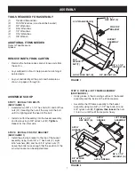
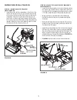
#10 x 5/8"
TRUSS
HEAD BOLT (L)
HOSE
CLIP (RR)
#10-32 NYLOCK
NUT (W)
FIGURE 17
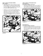
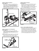
INSTALL FRONT SCOOP ON TRACTOR
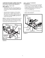
STEP 19: IDENTIFY YOUR TRACTOR TYPE
(SEE FIGURE 18)
•
Look underneath the front axle of your tractor. If there
is a single mower deck suspension bracket located
under the middle of the front axle, continue on to
step 20. If your tractor does not have a mower deck
suspension bracket underneath the middle of the
front axle, skip to step 22 on page 14 or step 24 on
page 14 for tractors with dual suspension brackets.
MOWER DECK
SUSPENSION
BRACKET
FIGURE 18
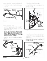
STEP 18: INSTALL HOSE CLIP AND SPACER
(SEE FIGURE 17)
• Secure the dump cable to the back of the bucket using
a hose clip (RR), a #10 x 5/8" truss-head bolt (L) and
a #10-32 nylock nut (W).
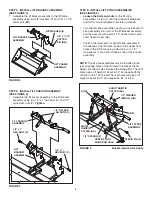
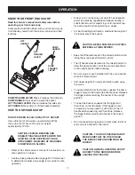
SPRING (NN)
SMALL 1/2" WASHER (GG)
CABLE
ADJUSTER
HOOK
DUMP CONTROL PIN
PIN STOP
BRACKET
3/4"
DUMP CONTROL PIN
PIN STOP
BRACKET
FIGURE 16
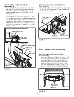
STEP 17: INSTALL DUMP CONTROL PIN
(SEE FIGURE 16)
• Install a small 1/2" washer (GG) and then the short
compression spring (NN) onto the dump control pin.
Install the dump control pin into the pin stop bracket.
Make sure the flat side of the pin faces to the front
when finished.
• Connect the hooked end of the dump cable into the
hole in the dump control pin. Install the threaded cable
adjuster down into the notch in the pin stop bracket,
placing a nut on each side of the notch. Adjust and
tighten the adjuster nuts so that the tapered end of the
dump control pin extends 3/4" through the side of the
pin stop bracket.
Summary of Contents for 486.248476
Page 22: ...22 NOTES ...

