background image

• Inspect tool cords periodically and if damaged, have them

repaired by an authorized service facility.

• Green (or green and yellow) conductor in cord is the

grounding wire. If repair or replacement of the electric cord
or plug is necessary, do not connect the green (or green
and yellow) wire to a live terminal.

• Where a 2-prong wall receptacle is encountered, it must be

replaced with a properly grounded 3-prong receptacle
installed in accordance with National Electric Code and
local codes and  ordinances.

WARNING:

This work should be performed by a qualified

electrician.
A temporary 3-prong to 2-prong grounding adapter (see
Figure 41) is available for connecting plugs to a two pole out-
let if it is properly grounded.

• Do not use a 3-prong to 2-prong grounding adapter unless

permitted by local and national codes and  ordinances.

• (A 3-prong to 2-prong grounding adapter is not permitted

in Canada.) Where permitted, the rigid green tab or termi-
nal on the side of the adapter must be securely connected
to a  permanent electrical ground such as a properly
grounded water pipe, a properly grounded outlet box or a
properly grounded wire system.

• Many cover plate screws, water pipes and outlet boxes are

not properly grounded. To ensure proper ground, grounding
means must be tested by a qualified  electrician.

EXTENSION CORDS

• The use of any extension cord will cause some drop in

voltage and loss of power.

• Wires of the extension cord must be of sufficient size to

carry the current and maintain adequate voltage.

• Use the table to determine the minimum wire size (A.W.G.)

extension cord.

• Use only 3-wire extension cords  having 3-prong grounding

type plugs and 3-pole receptacles which accept the tool plug.

• If the extension cord is worn, cut, or damaged in any way,

replace it  immediately.

Extension Cord Length (120V Operation)

Wire Size A.W.G.

Up to 25 ft.  . . . . . . . . . . . . . . . . . . . . . . . . . . . . . . . . . . . . . .14
Up to 50 ft.  . . . . . . . . . . . . . . . . . . . . . . . . . . . . . . . . . . . . . .12

NOTE:

Using extension cords over 50 ft. long is not

 recommended.

ELECTRICAL CONNECTIONS
WARNING:

Make sure unit is off and disconnected from

power source before inspecting any wiring.
The saw is prewired for use on a 120 volt, 60HZ power supply.
The power lines are inserted directly onto the switch. The
green ground line must remain securely fastened to the frame
to properly protect against electrical shock.

240 VOLT OPERATION

• To use the saw with a 240V, single-phase power supply,

have a qualified electrician attach a 240 volt, 15A 3-prong
plug onto saw line cord and install the proper connectors
and receptacles to power supply.

• See wiring diagram (Figure 42) for wiring instructions.

OPERATION

Refer to Figures 43-52, pages 15-18.

DESCRIPTION

The Craftsman 10

Model Number 218330  contractor saw

offers precise cutting performance for all woods up to 3

1

8

thick. The saw is designed for the professional user and is
ruggedly constructed for continuous service. The 10

Saw is

recommended for use with a 10

blade.

The saw features an extra large cast iron table. Saw body has
on board storage for push stick, miter gauge, rip fence and
saw blades. Saw is equipped with a riving knife and a clear
acrylic blade guard with anti-kickback feature. Cabinet is con-
structed of heavy gauge welded steel, totally enclosed and is
ported for a 4

vacuum hose. 

Rip Fence Assembly features a heavy-duty precision rip fence
that is designed for simple and one-hand maneuverability.
Front rail is calibrated in inches and millimeters with a magni-
fied window for close tolerances.

SPECIFICATIONS

Capacity with 10

Blade: 

Depth of cut at 90° . . . . . . . . . . . . . . . . . . . . . . . . . . . . . . . 3

1

8

Maximum tilt angle of arbor (left) . . . . . . . . . . . . . . . . . . . . 45°
Depth of cut at 45° . . . . . . . . . . . . . . . . . . . . . . . . . . . . . . 2

3

16

Max. cut right of blade with rip fence . . . . . . . . . . . . . . . . . 30

Max. cut left of blade with rip fence . . . . . . . . . . . . . . . . . . 13

Saw Dimensions:

Table height . . . . . . . . . . . . . . . . . . . . . . . . . . . . . . . . . . . 37

3

8

Cabinet depth . . . . . . . . . . . . . . . . . . . . . . . . . . . . . . . . . . . 22

Cabinet width. . . . . . . . . . . . . . . . . . . . . . . . . . . . . . . . . . 19½

Table area . . . . . . . . . . . . . . . . . . . . . . . . . . . . . . 26

5

16

x 20

3

16

Front of table to blade . . . . . . . . . . . . . . . . . . . . . . . . . . . 11

3

4

14

Figure 42 - Wiring Schematic

3

3

1

120V

240V

1

2

4

2

4

L1

L2

L1

L2

Figure 41 - 2-Prong Receptacle with Adapter

Make Sure
This Is
 Connected To
A Known
Ground

2-Prong Receptacle

Grounding Lug

Adapter

3-Prong Plug

Summary of Contents for 351.218330

Page 1: ...an 31105 04 Draft 02 09 10 Operator s Manual 10 CONTRACTOR TABLE SAW Model No 351 218330 CAUTION Read and follow all Safety Rules and Operating Instructions before First Use of this Product Keep this Manual with Tool Safety Unpacking Assembly Operation Maintenance Parts List Español ...

Page 2: ...e mask or dust mask if operation is dusty Be alert and think clearly Never operate power tools when tired intoxicated or when taking medications that cause drowsiness PREPARE WORK AREA FOR JOB Keep work area clean Cluttered work areas invite acci dents Do not use power tools in dangerous environments Do not use power tools in damp or wet locations Do not expose power tools to rain Work area should...

Page 3: ...he saw ON before clearing the table of all tools wood scraps etc except the workpiece and related feed or support devices for the operation planned Never place your face or body in line with the cutting tool Never place your fingers or hands in path of saw blade or other cutting tool For rip or rip type cuts the following end of a workpiece to which a push stick or push board is applied must be sq...

Page 4: ...otates toward you when standing in normal operating position Also make sure the cutting tool blade flange and arbor nut are installed properly Keep the cutting tool as low as possible for the operation being performed Keep all guards in place whenever possible Do not use any blade or other cutting tool marked for oper ating speed less than 4000 RPM Never use a cutting tool larger in diameter than ...

Page 5: ...arts Check for shipping damage or missing parts If any parts are damaged or missing call 1 800 266 9079 for replacement The table saw body comes assembled as one unit Additional parts which need to be fastened to the saw should be located and accounted for before assembling A Extension Table 2 B Dust Chute C Front Rail 2 D Rear Rail 2 E Miter Gauge Assembly F Blade Guard Assembly G Dado Insert H T...

Page 6: ... or cardboard on floor Place one of the handwheels onto the blade raise lower shaft located on the front of the cabinet Align the groove in the back of the handwheel with the pin Thread the washer and locking knob onto the threaded end of the shaft Repeat the steps above to assemble the remaining hand wheel and locking knob onto the blade tilt shaft located on the side of the cabinet REMOVE PACKIN...

Page 7: ... 10 Refer to Figures 10 and 11 place caster onto the bracket and secure in position with bolt and hex nut Repeat above steps for the second caster set ATTACH CASTER SETS TO BASE Refer to Figure 12 Tools Required 5mm Hex Wrench Hardware Required Eight M8 x 16 socket pan head screws Hardware bag 4 Attach one caster set to the two front corner supports using four M8 x 16 socket pan head screws Attach...

Page 8: ...efer to Figure 16 Tools Required 5mm Hex Wrench Hardware Required Two M6 x 16 socket head bolts two M6 flat washers and two M6 hex nuts Hardware bag 4 Install the rip fence storage brackets to the right side panel of the base using two bolts flat washers and hex nuts BLADE GUARD AND PUSH STICK STORAGE BRACKETS Refer to Figure 17 page 9 Tools Required Phillips screwdriver and 4mm hex wrench Hardwar...

Page 9: ...rbor and securely snug blade in position CHECK TABLE ALIGNMENT Refer to Figures 21 22 and 23 page 10 Saws are shipped from the factory with the table adjusted so the miter gauge slots are parallel to the saw blade However in order to obtain the best results from the saw it is suggested this adjustment be checked before operating A simple method of checking alignment is as follows Bolt or clamp a d...

Page 10: ...lts attach to the table extension Attach right front rail to the table and right table extension using flat washers lock washers and hex nuts NOTE Hand tighten all hardware during rail assembly Do not completely tighten hardware until all rails are mounted Attach left front rail in the same manner The two longer bolts attach to the table the two shorter bolts attach to table extension NOTE You may...

Page 11: ...ket holes Loosely attach flat washer lock washer and nut to bolts Insert bolt heads into T slot on bottom of left front rail Slide switch assembly 6 to 8 from left end of rail as shown in Figure 30 Fully tighten flat washers lock washers and hex nuts to secure switch assembly in place POSITION AND ADJUST RIVING KNIFE Refer to Figure 31 Riving knife is installed on the saw Raise the blade com plete...

Page 12: ...nto throat of table Insert is held in position by magnet in table To adjust insert level with table adjust leveling screws up or down ATTACH BLADE GUARD AND ANTI KICKBACK PAWLS Refer to Figures 33 36 page 12 and 13 Place the slot of blade guard body over the riving knife Slot of bushing is placed in the notch indicated in Figures 33 and 34 The bushings have a beveled edge and must be located in th...

Page 13: ...om electrical shock Check with a qualified electrician if grounding instructions are not understood or if in doubt as to whether the tool is properly grounded This tool is equipped with an approved 3 conductor cord rated at 300V and a 3 prong grounding type plug see Figure 40 for your protection against shock hazards Grounding plug should be plugged directly into a properly installed and grounded ...

Page 14: ... cords over 50 ft long is not recommended ELECTRICAL CONNECTIONS WARNING Make sure unit is off and disconnected from power source before inspecting any wiring The saw is prewired for use on a 120 volt 60HZ power supply The power lines are inserted directly onto the switch The green ground line must remain securely fastened to the frame to properly protect against electrical shock 240 VOLT OPERATIO...

Page 15: ...s the motor and may cause saw blade to loosen Never leave saw while the power is on To turn the table saw off press the large red OFF paddle Never leave saw until cutting tool has come to a complete stop The saw can be locked from unauthorized use by locking the switch To lock the switch Turn the switch to OFF position and disconnect saw from power source Pull the key out The switch cannot be turn...

Page 16: ...to Figure 46 The table insert must always be level with the saw table Place a straight edge across the front and rear of the table insert Check that the insert is perfectly level with the saw table To level the table insert turn one or more adjusting set screws as needed and recheck The table insert is equipped with two finger holes for easy removal MITER GAUGE ADJUSTMENT Refer to Figures 47 and 4...

Page 17: ... fence and turn either of the two adjusting screws NOTE This is for micro adjustment only If fence cannot be adjusted square recheck rail adjustment Lock fence in position and recheck Continue this proce dure until fence is square to the table PARALLEL ADJUSTMENT Position fence so that fence edge is aligned with slot edge Slot and fence edge should be parallel If an adjustment is necessary unlock ...

Page 18: ...th of the blade If the blade stalls or stops while cutting turn switch OFF and safety disconnect OFF before attempting to free the blade Do not reach over or behind the blade to pull the work piece through the cut to support long or heavy work pieces to remove small cut off pieces of material or for any other reason Do not pick up small pieces of cut off material from the table Remove them by push...

Page 19: ...ado set can vary width of cut up to 13 16 Instructions for operating dado set are contained in owner s manual furnished with dado set Dadoing requires cuts which do not go all the way through material Therefore blade guard must be removed Dado sets have different characteristics than saw blades As a result saw must be fitted with special parts that are furnished with saw Dado Insert Part No 31158 ...

Page 20: ...slowly rotate blade toward you until pin engages into arbor Hold arbor in locked position Place supplied open end wrench A on the arbor nut B Turn wrench counterclockwise to loosen nut Remove arbor nut blade flange C and saw blade D Place new blade on arbor Make sure saw blade teeth point down at the front side of saw table Place flange and nut on arbor and securely snug blade in position Replace ...

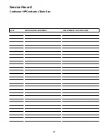
Page 21: ...21 Service Record Craftsman 10 Contractor Table Saw DATE MAINTENANCE PERFORMED REPLACEMENT PARTS REQUIRED ...

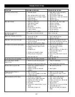
Page 22: ... 1 Motor overloaded 2 Fuses or circuit breakers do not have sufficient capacity 1 Rip fence out of alignment 2 Riving knife not aligned with blade 3 Feeding stock without rip fence 4 Riving knife not in place 5 Dull blade 6 Letting go of material before it is past blade 7 Anti kickback fingers dull CORRECTIVE ACTION 1 Allow motor to cool and reset by pushing reset switch 2 Check all plug connectio...

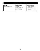
Page 23: ...t POSSIBLE CAUSE S 1 Dull blade 2 Blade mounted backwards 3 Gum or pitch on blade 4 Incorrect blade for cut 5 Gum or pitch on table CORRECTIVE ACTION 1 Sharpen or replace blade 2 Turn blade around 3 Remove blade and clean 4 Change blade to correct type 5 Clean table ...

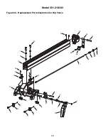
Page 24: ...24 Model 351 218330 Figure 55 Replacement Parts Illustration for Rip Fence 26 13 24 11 11 12 2 1 3 3 4 5 6 14 27 28 29 25 30 31 15 7 8 8 10 10 19 18 17 16 20 21 22 23 9 9 ...

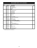
Page 25: ...ting Screw 2 12 31115 00 Base 1 13 31116 00 Nylon Screw 2 14 31117 00 Lens 2 15 STD851004 4mm Flat Washer 2 16 06177 00 4 0 7 x 8mm Flat Head Screw 2 17 31118 00 Fence 1 18 STD851008 8mm Flat Washer 2 19 STD852008 8mm Lock Washer 2 20 STD870820 8 1 25 x 20mm Socket Head Bolt 2 21 31119 00 3 5 1 3 x 10mm Threadforming Screw 2 22 31120 00 Cap 1 23 31121 00 Latch 1 24 18782 00 10 x 50mm Spring Pin 1 ...

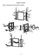
Page 26: ...26 Model 351 218330 Figure 56 Replacement Parts Illustration for Cabinet 10 11 12 14 8 2 2 5 6 7 8 2 3 3 17 6 16 15 25 23 18 19 20 4 9 1 2 2 7 5 21 22 24 13 ...

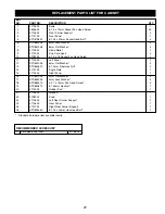
Page 27: ... 2 10 09789 00 6 1 0 x 16 Socket Pan Head Screw 2 11 31130 00 Left Panel 1 12 STD851006 6mm Flat Washer 2 13 STD843610 6 1 0mm Fiber Hex Nut 2 14 31131 00 Angle Plate 1 15 31132 00 Right Panel 1 16 STD851004 4mm Flat Washer 4 17 STD852004 4mm Lock Washer 4 18 STD863410 4 0 7 x 10mm Pan Head Screw 4 19 STD840812 8 1 25mm Hex Nut 1 20 31133 00 Rubber Pad 1 21 31134 00 Wrench 1 22 31282 00 Knob 1 23 ...

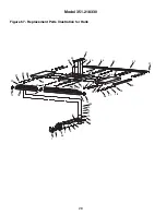
Page 28: ... 351 218330 Figure 57 Replacement Parts Illustration for Rails 31 32 33 28 30 29 27 26 24 24 24 25 25 25 41 7 39 38 36 37 35 21 23 14 13 21 20 15 22 23 23 2 6 8 9 1 10 11 12 19 18 16 17 45 3 4 5 43 40 44 34 42 ...

Page 29: ...il Cap 1 20 31146 00 Scale 2 piece 1 21 STD835025 8 1 25 x 25mm Hex Head Bolt 8 22 31147 00 8 1 25 x 28mm Hex Head Bolt 8 23 STD851008 8mm Flat Washer 16 24 STD852008 8mm Lock Washer 16 25 STD840812 8 1 25mm Hex Nut 16 26 STD835020 8 1 25 x 20mm Hex Head Bolt 4 27 STD851008 8mm Flat Washer 4 28 STD852008 8mm Lock Washer 4 29 STD845812 8 1 25mm Cap Nut 4 30 31148 00 Brace 1 31 31149 00 Right Rear R...

Page 30: ...18330 Figure 58 Replacement Parts Illustration for Base 19 20 21 24 23 22 25 13 18 6 6 6 17 16 13 13 15 1 1 2 1 13 4 9 4 4 4 3 2 2 3 5 5 5 5 5 5 5 2 1 7 7 7 7 8 9 6 8 3 28 28 34 27 26 26 32 31 30 29 29 33 10 11 14 12 ...

Page 31: ...x 16mm Socket Head Bolt 2 15 STD870512 5 0 8 x 12mm Socket Head Bolt 4 16 STD852005 5mm Lock Washer 4 17 STD851005 5mm Flat Washer 4 KEY NO PART NO DESCRIPTION QTY 18 31171 00 Blade Guard Bracket Front 1 19 31172 00 Blade Guard Bracket Rear 1 20 22462 00 3 0 5 x 10mm Pan Head screw 4 21 04491 00 3mm Lock Washer 4 22 05981 00 3mm Flat Washer 4 23 31173 00 Push Stick Bracket 1 24 31174 00 Push Stick...

Page 32: ...3 47 40 74 70 71 72 73 41 65 75 76 77 78 79 79 81 82 83 84 85 87 88 16 17 56 53 46 45 44 30 43 31 29 27 30 86 80 50 51 49 16 52 17 54 55 17 42 66 67 68 69 38 39 60 62 61 37 35 23 2 1 3 19 18 17 16 14 15 48 4 5 Model 351 218330 64 63 Figure 59 Replacement Parts Illustration for Blade Drive ...

Page 33: ...olt 4 39 31200 00 3CMI 3 5 Retaining Ring 1 40 STD843550 3 0 5mm Fiber Hex Nut 1 41 31201 00 Adjustment Latch 1 42 31202 00 3 0 5 x 18mm Pan Head Screw 1 43 31203 00 Bushing 1 44 31204 00 Bevel Plate 1 KEY NO PART NO DESCRIPTION QTY 45 07383 00 3CMI 9 Retaining Ring 1 46 31205 00 Spacer 1 47 31206 00 Bracket 1 48 31207 00 Pin 2 49 31208 00 Spring 1 50 31209 00 Lock Pin 1 51 31210 00 Riving Knife 1...

Page 34: ...6 34 7 7 8 9 10 11 12 13 20 20 21 21 22 22 35 28 25 26 27 24 29 31 30 32 33 5 4 4 37 36 9 23 2 2 2 1 3 3 19 18 17 16 16 14 15 15 15 4 Model 351 218330 Figure 60 Replacement Parts Illustration for Blade Guard ...

Page 35: ... 13 N A Bushing Plate 1 14 N A Pivot Pin 1 15 N A 4 x 12mm Spring Pin 3 16 N A Latch 2 17 N A 3 0 5 x 8mm Set Screw 1 18 N A Spring 1 19 N A Pivot Pin 1 20 N A 3CMI 9 Retaining Ring 2 21 N A Pawl 2 22 N A Bushing 2 23 N A Support 1 24 31253 00 Knob 1 25 N A Spacer 1 26 31255 00 Miter Gauge 1 27 STD840508 5 0 8mm Hex Nut 3 28 STD863520 5 0 8 x 20mm Pan Head Screw 3 29 STD863410 4 0 7 x 10mm Pan Hea...

Page 36: ...that you need to do it yourself For Sears professional installation of home appliances and items like garage door openers and water heaters 1 800 4 MY HOME 1 800 469 4663 Call anytime day or night U S A and Canada www sears com www sears ca Our Home For repair of carry in items like vacuums lawn equipment and electronics call anytime for the location of your nearest Sears Parts Repair Service Cent...

Reviews: