background image

MAINTENANCE AND REPAIR INSTRUCTIONS

AIR FILTER

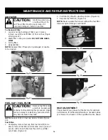
To Clean Air Filter:

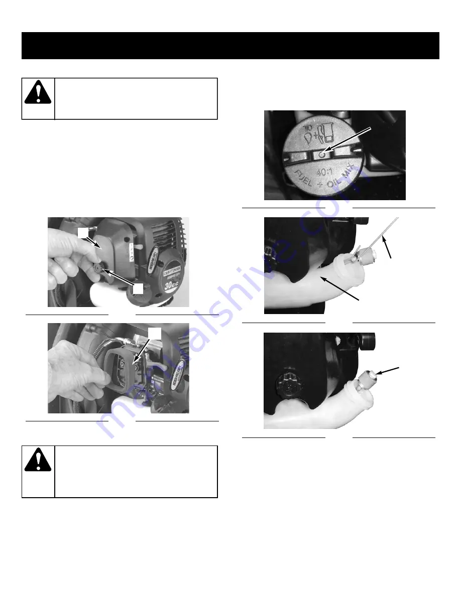
1. Loosen knob (A) holding air filter cover in place,

remove cover (B) and lift filter (C) from air box (Figure
20 & Figure 21).

2. Wash filter in soap and water. 

DO NOT USE GASO-

LINE!

3. Air dry filter.
4. Reinstall filter.

NOTE:

Replace filter if frayed, torn, damaged or unable

to be cleaned.

FUEL CAP / FUEL FILTER

NOTE:

Keep vent (A) on fuel cap clean of debris (Figure

22).

Fuel Filter:

1. Completely remove fuel cap from fuel tank (B) to be

able to remove fuel filter (C) from tank. Use a piece of
wire (C) with a hook formed at the end to pull filter
out of tank. (Figure 23)

2. Pull filter (D) off with a twisting motion. (Figure 24)
3. Replace fuel filter (D). (Figure 24)

NOTE:

Never operate the blower without the fuel filter.

Internal engine damage could result!

IDLE ADJUSTMENT

The carburetor was pre-set at the factory for optimum
performance. If further adjustments are necessary take
your blower to a Sears or other qualified service dealer.

NEVER operate blow-
er without the air fil-

ter. The air filter must be kept clean. If it
becomes damaged, install a new filter.

CAUTION:

Remove fuel from unit
and store in approved

container before starting this procedure. Open
fuel cap slowly to release any pressure which
may have formed in fuel tank.

CAUTION:

Fig. 20

Fig. 21

B

A

C

Fig. 22

Fig. 23

Fig. 24

A

C

B

D

14

Summary of Contents for 316.79499

Page 1: ...Y ASSEMBLY OPERATION MAINTENANCE PARTS LIST CAUTION Before using this product read this manual and follow all safety rules and oper ating instructions Sears Roebuck and Co Hoffman Estates IL 60179 U S A Visit our website www sears com craftsman with 9096 320601 date 12 04 ...

Page 2: ...CAUSE CANCER BIRTH DEFECTS OR OTHER REPRODUCTIVE HARM CALIFORNIA PROPOSITION 65 WARNING TABLE OF CONTENTS Warranty Page 2 Safety Rules Pages 3 8 Assembly Page 9 Starting Stopping instrustion Pages 10 11 Operation Page 12 TWO YEAR LIMITED WARRANTY ON CRAFTSMAN GAS BACKPACK BLOWER For two years from the date of purchase when this Blower is used and maintained according to the operator s manual Sears...

Page 3: ...t be installed properly before operating the unit Inspect the unit before use Replace damaged parts Check for fuel leaks Make sure all fasteners are in place and secure Replace parts that are cracked chipped or damaged in any way Do not operate the unit with loose or damaged parts Carefully inspect the area before starting the unit Remove all debris and hard or sharp objects such as glass wire etc...

Page 4: ...ys hold the unit with a firm grip when operating Keep hands face and feet away from all moving parts Do not touch or try to stop the impeller when it is rotat ing Do not operate without guards in place Do not put any object into openings Do not use with any opening blocked keep free of dirt debris and any thing that may reduce the air flow Do not touch the engine or muffler These parts get extreme...

Page 5: ...er to them often and use them to instruct other users If you loan this unit to oth ers also loan these instructions to them SPECIAL NOTE Exposure to vibrations through pro longed use of gasoline powered hand tools could cause blood vessel or nerve damage in the fingers hands and joints of people prone to circulation disorders or abnormal swelling Prolonged use in cold weather has been linked to bl...

Page 6: ...ays use clean fresh unleaded fuel OIL Refer to operator s manual for the proper type of oil SYMBOL MEANING ON OFF CONTROL ON START RUN ON OFF CONTROL OFF OR STOP RED CHOKE LEVER POSITIONS 1 FULL Choke Position 2 PARTIAL Choke Position 3 RUN Position SAFETY AND INTERNATIONAL SYMBOLS This operator s manual describes safety and international symbols and pictographs that may appear on this product Rea...

Page 7: ...7 STARTER HANDLE 8 AIR CLEANER COVER 9 FUEL CAP 10 FUEL TANK 11 PRIMER BULB 12 HARNESS 13 CONTROL HANDLE 14 OPERATING TUBE 15 HOSE CLAMP 16 FLEX TUBE 17 THROTTLE LINKAGE 18 MUFFLER COVER 19 SPARK ARRESTER SCREEN 20 VENTED BACK PAD 21 INTERMEDIATE TUBE 22 56mm NOZZLE 23 45mm CONCENTRATOR NOZZLE 24 THROTTLE LINKAGE CLIPS 7 21 22 23 1 2 3 4 5 6 7 8 9 10 11 12 19 18 20 17 16 15 14 13 24 ...

Page 8: ...ml of fuel additive per gallon of fuel according to the instructions on the container NEVER add fuel additives directly to the unit s fuel tank To Obtain Correct Fuel Mix Thoroughly mix the proper ratio of 2 cycle engine oil with unleaded gasoline in a separate fuel can Use a 40 1 fuel oil ratio Do not mix them directly in the engine fuel tank See the table below for specific gas and oil mixing ra...

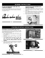
Page 9: ...mp is positioned away from operator 2 Turn the rotary ring mark D align the throttle handle F Then insert the operating tube E into the flexible tube B Fig 3 with a hose clamp G Fig 4 and tighten securely 3 Attache throttle linkage clips 24 know your blower to both ends of the flex tube See Fig 5 and Fig 6 ASSEMBLY INSTRUCTIONS Fig 1 B A Fig 2 C Fig 5 Fig 6 Fig 3 Fig 4 F B E G 9 THROTTLE LINKAGE C...

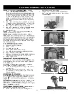
Page 10: ...ack harness and control handle Fig 7 B D H I 45mm 56mm Fig 8 STARTING STOPPING INSTRUCTIONS Fig 9 A C B Fig 11 D 10 STARTING A COLD ENGINE Above 55 F Fill fuel tank with proper gas and oil mixture See FUEL AND LUBRICATION Set unit upright on ground so that it rests on the back pack frame 1 Move on off ignition switch A to the RUN I posi tion Figure 9 2 Pump primer bulb10 X by pushing up on the bul...

Page 11: ...w 55 F 1 Switch to RUN I position 2 Prime 10 times 3 Choke in position 4 Do not press throttle lock or trigger 5 Pull rope until engine starts should be 1 10 times 6 Move choke to position 7 After unit starts apply 1 4 throttle slightly and slowly then allow engine to warm up for 30 seconds 8 Press trigger to run IMPORTANT IDLING INFORMATION In some cases due to operating conditions altitude tem p...

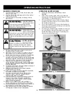
Page 12: ...areas such as gutters screens patios grills porches and gardens 13 Watch out for children pets open windows or freshly washed cars and blow debris safely away 14 Use intermediate tube plus nozzle of your choice so the airstream can work close to the ground 15 After using blowers and other equipment CLEAN UP Dispose of debris in trash receptacles OPERATION INSTRUCTIONS 1 Follow the instructions STA...

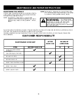
Page 13: ...ance or repairs with unit running Always service and repair a cool unit Disconnect the spark plug wire to ensure that the unit cannot start WARNING A good preventive maintenance program of regular inspection and care will increase life and improve performance of your chain saw This maintenance checklist is a guide for such a program Cleaning adjustment and part replacement may be required under ce...

Page 14: ...at the end to pull filter out of tank Figure 23 2 Pull filter D off with a twisting motion Figure 24 3 Replace fuel filter D Figure 24 NOTE Never operate the blower without the fuel filter Internal engine damage could result IDLE ADJUSTMENT The carburetor was pre set at the factory for optimum performance If further adjustments are necessary take your blower to a Sears or other qualified service d...

Page 15: ... following storage 1 Perform all the general maintenance recommended in the Maintenance Section of your User Manual 2 Clean exterior of engine and blower tubes 3 Drain fuel from the fuel tank by running the unit dry or by removing the fuel cap and tipping the motor hous ing fuel tank over and draining oil fuel mixture into a container with the same 2 cycle fuel mixture 4 After fuel is drained star...

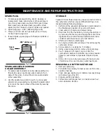
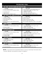
Page 16: ...IT WON T START OR STARTS BUT WILL NOT RUN UNIT STARTS BUT ENGINE HAS LOW POWER ENGINE HESITATES NO POWER UNDER LOAD C A U S E A C T I O N 1 Fuel filter is plugged 1 Replace the fuel filter 2 Incorrect lever position 2 Move to Position 3 3 Dirty spark arrestor screen 3 Replace spark arrestor screen 4 Dirty air filter 4 Remove clean and reinstall filter 5 Incorrect carburetor mixture adjustment sett...

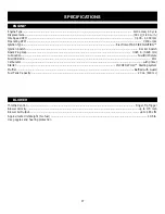
Page 17: ... Switch Rocker Switch Spark Plug Gap 0 025 in 0 635 mm Lubrication Fuel Oil Mixture Fuel Oil Ratio 40 1 Carburetor with primer Starter INCREDI PULL Starting system Muffler Baffled with Guard Fuel Tank Capacity 20 oz 600 ml Throttle Control Finger Tip Trigger Blower Velocity up to 170 mph Blower Air Output up to 485 cfm Approximate Unit Weight No fuel 19 5 lb Use goggles and hearing protection 17 ...

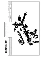
Page 18: ...DATE 11 19 2004 SPECIFY MODEL NO WHEN ORDERING PARTS 30CC BACK PACK BLOWER MODEL NO 79499 41AR322G799 REVISED DATE PAGE N A 1 2 SERVICE SPARE PARTS LIST ...

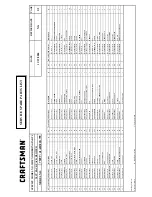
Page 19: ...01 GASKET 1 43 1 MC 9151 334502F CRANKCASE STARTWE SIDE 1 69 MC 9RGP7 14 16 27 RIVET RIBBED 1 16 MC 9189 334501 PISTON RING 2 43 2 MC 9PC03 08 PIN 3 70 MC 9149 320601 HARNESS 1 17 MC 9131 334501 CIRCLIP 2 43 3 MC 9151 334501F CRANKCASE FLYWHEEL SIDE 1 71 MC 9NHB 06 NUT 1 18 MC 9115 334501 PISTON PIN 1 43 4 MC 9SGEB 05 20 SCREW 3 72 MC 9SKKB 06 15 SCREW 1 19 MC 9290 334501 PISTON 1 44 MC 9DB 620101...

Page 20: ...ilities you should call 1 800 4 MY HOME Manufacturer s Warranty Coverage The warranty period begins on the date the engine or equipment is delivered to the retail purchaser The manufacturer warrants to the initial owner and each subsequent purchaser that the engine is free from defects in mate rial and workmanship which cause the failure of a warranted part for a period of two years Repair and rep...

Page 21: ...21 ...

Page 22: ......

Reviews: