background image

31

7-1/4 in. COMPOUND MITER SA

W – MODEL NUMBER 315.BT2010

The 

model 

number will be 

found 

on 

label attached to 

the 

motor 

housing. 

Always 

mention the model 

number in all corr

espondence 

regar

ding 

your 

7-1/4 in. COMPOUND MITER SA

or when or

dering parts.  

PAR

TS LIST FOR FIGURE A


KEY


PAR

T


NO.


NUMBER


DESCRIPTION


QTY


KEY


PAR

T


NO.


NUMBER


DESCRIPTION


QTY


089100401706


D-Handle Assembly

 ......................................

1


089100401905


W

ar

ning Label

 ...............................................

1


089240001052


Scr

ew (M5 x 30 mm, Pan Hd.)

 ......................

3


089240001093


Scr

ew (M4 x 16 mm)

 .....................................

5


089100401902


Blade (7-1/4 in. x 24t)

 ...................................

1


089100401907


Hang T

ag W

ar

ning (Spanish)

 .........................

1


080001020713


Switch, Brush and Contact


Plate Assembly

 .............................................

1


089100401017


Trigger

 ...........................................................

1


080006014060


Compr

ession Spring

 .....................................

1


10


080001020037


Scr

ew (M5 x 15 mm)

 .....................................

2


11


080001020038


Scr

ew (M4 x 38 mm)

 .....................................

2


12


089100401016


Safety Buckle Cover

 .....................................

1


13


089240001057


Safety Buckle

 ................................................

1


14


089240001059


Scr

ew (M3 x 12 mm)

 .....................................

1


15


089240001060


Spring

 ...........................................................

1


16


089100401908


Dust Bag

 .......................................................

1


17


080001020708 


Upper Guar

d/Gear Box and Motor 


Assembly (Inc. Key Nos. 2, 18-19, 31)

 ..........

1


18


089100401904


Logo Label

 ....................................................

1


19 

089240001907 

W

ar

ning

 Label合

合合 (Pivot

 Plate

 Scr

ew)

 ................

1


20


089240001041


Set Scr

ew (M4 x 8 mm, Nylock)

 ...................

2


21


089240001037


Dust 

Cover

 ....................................................

1


22


089240001038


Scr

ew (M4 x 22 mm, Pan Hd.)

 ......................

1


23


089100302038


Scr

ew (M4 x 8 mm, Pan Hd.)

 ........................

1


24


589032207


Stop Block

 ....................................................

1


25


089240001038


Scr

ew (M4 x 18 mm, Pan Hd.)

 ......................

2


26


089240001044


Bearing Holder Plate

 .....................................

1


27


080001020703


Gear and Spindle Assembly

 .........................

1


28


089240001071


Blade Bolt

 .....................................................

1


29


080009002060


Blade W

asher

 ................................................

2


30


080001020708


Blade Guar

d Assembly

 .................................

1


31


089100401901


Data Label

 .....................................................

1


32


089100207027


Scr

ew (M3, Shoulder)

 ...................................

1


33


089240001064


Scr

ew (M5 x 5 mm, Shoulder)

 ......................

1


34


A19001040091


Scr

ew (M4 x 9 mm, Pan Hd.)

 ........................

1


Not Shown:


990000668


Operator’

s Manual

 ........................................

1

Summary of Contents for 315.BT2010

Page 1: ...s consultas WARNING To reduce the risk of injury the user must read and understand the operator s manual before using this product Customer Help Line 1 800 932 3188 Teléfono de atención al consumidor 1 800 932 3188 Sears Brands Management Corporation 3333 Beverly Rd Hoffman Estates IL 60179 USA Visit the Craftsman web page www sears com craftsman Visite el sitio web de Craftsman www sears com craf...

Page 2: ...y defects in material or workmanship With proof of purchase defective product will be replaced free of charge For warranty coverage details to obtain free replacement visit the web site www craftsman com This warranty does not cover the bits which are expendable parts that can wear out from normal use within the warranty period This warranty is void if this product is ever used while providing com...

Page 3: ...for better and safer performance Follow instructions for lubricating and changing accessories USE RECOMMENDED ACCESSORIES Consult the operator s manual for recommended accessories The use of improper accessories may result in injury NEVER STAND ON TOOL Serious injury could occur if the tool is tipped or if the cutting tool is unintention ally contacted CHECK DAMAGED PARTS Before further use of the...

Page 4: ...HE WORK PIECE DO NOT OPERATE A TOOL WHILE UNDER THE INFLUENCE OF DRUGS ALCOHOL OR ANY MEDICATION WHEN SERVICING use only identical replacement parts Use of any other parts may create a hazard or cause product damage DOUBLE CHECK ALL SETUPS Make sure blade is tight and not making contact with saw or workpiece before connecting to power supply ENSURE THE SWITCH IS IN THE OFF POSITION BEFORE INSERTIN...

Page 5: ...t severe injury MAKE SURE THE WORK AREA HAS AMPLE LIGHT ING to see the work and that no obstructions will inter fere with safe operation BEFORE performing any work using your saw THIS TOOL should have the following markings a Wear eye protection b Keep hands out of path of saw blade c Do not operate saw without guards in place d Do not perform any operation freehand e Never reach around saw blade ...

Page 6: ...way from the blade will result in serious personal injury Wet Conditions Alert min Per Minute no No Load Speed min Minutes V Volts Always wear eye protection with side shields marked to comply with ANSI Z87 1 The following signal words and meanings are intended to explain the levels of risk associated with this product SYMBOL SIGNAL MEANING DANGER Indicates an imminently hazardous situation which ...

Page 7: ...ial The item on which the operation is being done Worktable Surface where the workpiece rests while performing a cutting drilling planing or sanding operation Anti KickbackPawls flooring radialarm andtablesaws A device which when properly installed and maintained is designed to stop the workpiece from being kicked back toward the front of the saw during a ripping operation Arbor The shaft on which...

Page 8: ...vel 0 Maximum lumber sizes 1 1 2 in x 3 in Cutting Capacity with Miter at 0 Bevel 45 Maximum lumber sizes 1 1 2 in x 3 1 2 in Cutting Capacity with Miter at 45 Bevel 45 Maximum lumber sizes 1 1 2 in x 3 in LOWER BLADE GUARD UPPER BLADE GUARD D HANDLE BASE MITER LOCK LEVER BEVEL LOCK KNOB SWITCH TRIGGER THROAT PLATE NO HANDS ZONE LABEL NO HANDS ZONE BOUNDARY LINE MITER SCALE BLADE WRENCH MITER TABL...

Page 9: ... miter fence on the compound miter saw has been provided to hold your workpiece securely against when making all cuts MITER LOCK LEVER See Figure 2 The miter lock lever securely locks the saw at desired miter angles POSITIVE STOPS ON MITER TABLE Positive stops have been provided at 0 15 22 1 2 31 62 and 45 The 15 22 1 2 31 62 and 45 positive stops have been provided on both the left and right side...

Page 10: ...h in the off position To lock the switch install a padlock not includ ed through the hole in the switch trigger A lock with a long shackle of 5 16 in diameter may be used When the lock is installed and locked the switch is inoperable Store the padlock key in another location The following tools not included or drawn to scale are needed for making adjustments or installing the blade TOOLS NEEDED Fi...

Page 11: ...ot listed might be hazardous and could cause serious personal injury The following items are included with your compound miter saw Dust Bag Work Clamp Blade Wrench WORK CLAMP DUST BAG BLADE WRENCH REAR BRACKET CARRYING HANDLE Rear Bracket Carrying Handle Operator s Manual not shown ...

Page 12: ... should remain on the saw arm to prevent sudden rise upon release of the tie wrap Inspect the tool carefully to make sure no breakage or damage occurred during shipping Do not discard the packing material until you have carefully inspected and satisfactorily operated the tool The saw is factory set for accurate cutting After assembling it check for accuracy If shipping has influenced the settings ...

Page 13: ...lts securely The hole pattern for mounting to a workbench is shown in figure 8 Carefully check the workbench after mounting to make sure that no movement can occur during use If any tipping sliding or walking is noted secure the workbench to the floor before operating TRACE HOLES AT THESE LOCATIONS FOR HOLE PATTERN Fig 8 MOUNTING SURFACE BASE TRACE HOLES AT THESE LOCATIONS FOR HOLE PATTERN 45 30 3...

Page 14: ...se a C clamp instead of the work clamp to secure the workpiece prior to making the cut WARNING In some operations the work clamp assembly may interfere with the operation of the blade guard assembly Always make sure there is no interference with the blade guard prior to beginning any cutting operation to reduce the risk of serious personal injury To install the work clamp Place the shaft of the wo...

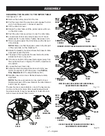
Page 15: ...e they contact the blade WARNING If inner blade washer has been re moved replace it before placing blade on spindle Failure to do so could cause an accident since blade will not tighten properly Fig 12 SPINDLE LOCK BUTTON Fig 11 45 NOTE BEFORE USE REPLACE SCREW AND TIGHTEN SECURELY TO PREVENT GUARD MOVEMENT LOWER BLADE GUARD BLADE OUTER BLADE WASHER WITH DOUBLE D FLATS BLADE BOLT TO LOOSEN BLADE B...

Page 16: ...aw blade not the blade teeth The edge of the square and the saw blade should be parallel as shown in figure 14 If the front or back edge of the saw blade angles away from the square as shown in figures 15 and 16 adjust ments are needed Using the blade wrench loosen the socket head screws that secure the miter fence to the miter table See figure 13 Rotate the miter fence left or right until the saw...

Page 17: ...ade not the blade teeth Rotate the blade by hand and check the blade to table alignment at several points The edge of the square and the saw blade should be parallel as shown in figure 18 If the top or bottom of the saw blade angles away from the square as shown in figures 19 and 20 adjustments are needed Loosen the bevel lock knob Adjust positive stop adjustment screw to bring saw blade into alig...

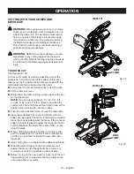
Page 18: ...and Never operate the miter saw on the floor or in a crouched position Failure to heed this warning can result in serious personal injury WARNING To avoid serious personal injury always lock the miter lock lever before making a cut Failure to do so could result in movement of the control arm or miter table while making a cut WARNING To avoid serious personal injury keep hands outside the no hands ...

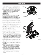
Page 19: ...the miter lock lever Rotate the miter table until the pointer aligns with zero on the miter scale NOTE You can quickly locate 0 15 22 1 2 left or right 31 62 and 45 left or right as you rotate the control arm The miter table will seat itself in one of the positive stop index points located in base Push the miter lock lever down to lock the miter table Place the workpiece flat on the miter table wi...

Page 20: ...ts located in base Push the miter lock lever down to lock the miter table Loosen the bevel lock knob and move the saw arm to the left to the desired bevel angle Bevel angles can be set from 0 to 45 Align the indicator point for the desired angle Once the saw arm has been set at the desired angle securely tighten the bevel lock knob Place the workpiece flat on the miter table with one edge securely...

Page 21: ... change the effect of the bevel setting Also each time you adjust the bevel setting you change the effect of the miter setting It may take several settings to obtain the desired cut The first angle setting should be checked after setting the second angle since adjusting the second angle affects the first Once the two correct settings for a particular cut have been obtained always make a test cut i...

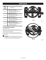
Page 22: ...efore turning on the saw perform a dry run of the cut ting operation just to make sure that no problems will occur when the cut is made Grasp the saw handle firmly Depress the switch lock with thumb then squeeze the switch trigger Allow sev eral seconds for the blade to reach maximum speed Slowly lower the blade into and through the workpiece Release the switch trigger and allow the saw blade to s...

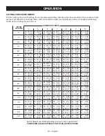
Page 23: ...2 B 4 59 M 34 32 B 11 60 M 28 48 B 9 85 M 24 35 B 8 53 M 21 27 B 7 52 M 18 88 B 6 72 M 16 98 B 6 07 M 33 36 B 14 38 M 27 62 B 12 20 M 23 56 B 10 57 M 20 58 B 9 31 M 18 26 B 8 31 M 16 41 B 7 50 M 32 18 B 17 09 M 26 57 B 14 48 M 22 64 B 12 53 M 19 73 B 11 03 M 17 50 B 9 85 M 15 72 B 8 89 M 30 76 B 19 70 M 25 31 B 16 67 M 21 53 B 14 41 M 18 74 B 12 68 M 16 60 B 11 31 M 14 90 B 10 21 M 29 10 B 22 20 M...

Page 24: ... of the miter saw CEILING W A L L INSIDE CORNER CROWN MOLDING FLAT ON MITER TABLE 38 52 FENCE MITER TABLE BOTTOM EDGE AGAINST FENCE RIGHT SIDE INSIDE CORNER LEFT SIDE OUTSIDE CORNER FENCE MITER TABLE Fig 29 OUTSIDE CORNER TOP EDGE AGAINST FENCE LEFT SIDE INSIDE CORNER RIGHT SIDE OUTSIDE CORNER CUTTING CROWN MOLDING This compound miter saw does an excellent job of cutting crown molding In general c...

Page 25: ...nst fence 2 Miter table set right 31 62 3 Save right end of cut 33 85 33 85 33 85 33 85 CUTTING WARPED MATERIAL See Figures 30 31 When cutting warped material always make sure it is positioned on the miter table with the convex side against the fence as shown in figure 30 If the warped material is positioned the wrong way as shown in figure 31 it will pinch the blade near the comple tion of the cu...

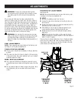
Page 26: ...itself or if there is play in the pivot joints have saw repaired by at your nearest authorized service center BEVEL PIVOT ADJUSTMENT The compound miter saw should bevel easily by loos ening the bevel lock knob and tilting the saw arm to the left If movement is tight or if there is play in the pivot have saw repaired by at your nearest authorized service center Fig 32 POSITIVE STOP ADJUSTMENT SCREW...

Page 27: ...t and secure Considerable effort should be required to move the miter table If the table moves easily when in the locked position an adjustment of the miter lock lever is required To adjust Unplug the saw Lock the miter lock lever completely Pull the miter lock lever out to the right to disengage then rotate forward to adjust Release miter lock lever to re engage Recheck the miter table to ensure ...

Page 28: ...ubject to acceler ated wear and possible premature failure because the fiberglass chips and grindings are highly abrasive to bear ings brushes commutators etc Consequently we do not recommend using this tool for extended work on these types of materials However if you do work with any of these materials it is extremely important to clean the tool using compressed air LUBRICATION All of the bearing...

Page 29: ...29 English NOTES ...

Page 30: ...30 7 1 4 in COMPOUND MITER SAW MODEL NUMBER 315 BT2010 FIGURE A 34 28 33 25 18 21 22 23 24 20 16 29 5 17 19 32 27 26 29 13 14 15 4 4 9 8 7 10 4 3 6 1 1 11 12 31 2 30 ...

Page 31: ...crew M4 x 38 mm 2 12 089100401016 Safety Buckle Cover 1 13 089240001057 Safety Buckle 1 14 089240001059 Screw M3 x 12 mm 1 15 089240001060 Spring 1 16 089100401908 Dust Bag 1 17 080001020708 Upper Guard Gear Box and Motor Assembly Inc Key Nos 2 18 19 31 1 18 089100401904 Logo Label 1 19 089240001907 Warning Label合 成紙 Pivot Plate Screw 1 20 089240001041 Set Screw M4 x 8 mm Nylock 2 21 089240001037 ...

Page 32: ...D MITER SAW MODEL NUMBER 315 BT2010 FIGURE B 47 53 52 52 46 45 44 51 50 42 43 34 35 35 31 33 32 28 22 21 15 14 14 6 5 4 3 1 2 7 8 9 10 11 30 27 26 24 23 13 36 19 20 25 12 16 39 38 49 49 37 22 37 22 41 40 54 55 17 18 48 29 ...

Page 33: ...g Washer M8 3 23 089100207038 Screw M4 x 8 mm 5 24 089100401006 Throat Plate 1 25 080006014010 Lock Nut M8 1 26 089240001087 Washer ID8 2 x OD20 x 1 5t 1 27 080001020007 Washer ID8 2 x OD26 x 1 5t 1 28 089100401005 Table 1 29 089240001007 Screw M5 Shoulder 1 30 089100401906 Bevel Scale 1 31 089240001015 Miter Pointer 1 32 089240001017 Washer M3 2 33 089240001016 Screw M3 x 10 mm Pan Hd 2 34 089240...

Page 34: ...herramienta NO ESTIRE EL CUERPO PARA ALCANZAR MAYOR DISTANCIA Mantenga una postura firme y buen equilibrio en todo momento DÉ MANTENIMIENTO CON CUIDADO A LAS HERRAMIENTAS Mantenga afiladas y limpias las herramientas para obtener de las mismas un desempeño mejor y más seguro Siga las instrucciones correspondientes al cambio y lubricación de accesorios USE ACCESSORIOS RECOMENDADOS Consulte este manu...

Page 35: ... SI SE ENCUENTRA BAJO LOS EFECTOS DE DROGAS ALCOHOL O MEDICAMENTOS AL DAR SERVICIO a la unidad sólo utilice piezas de repuesto idénticas El empleo de piezas diferentes puede causar un peligro o dañar el producto REVISE DOS VECES TODA CONFIGURACIÓN DE LA HERRAMIENTA Asegúrese de que la hoja esté apretada y de que no toque la sierra o la pieza de trabajo antes de conectar la unidad al suministro de ...

Page 36: ...ar el trabajo SIEMPRE PERMANEZCA ALERTA No permita que su familiaridad con la máquina proveniente del uso frecuente de la sierra sea causa de un error de descuido SIEMPRE TENGA PRESENTE que un descuido de un instante es suficiente para causar una lesión grave ASEGÚRESE DE QUE EL ÁREA DE TRABAJO CUENTE CON SUFICIENTE ILUMINACIÓN para ver la pieza de trabajo y de que ninguna obstrucción interfiera e...

Page 37: ...producto Tiempo min Minutos Velocidad de rotación en vacío no Velocidad en vacío Revoluciones carreras velocidad superficial órbitas etc por minuto min Por minuto Voltaje V Volts Siempre póngase protección ocular con la marca de cumplimiento de la norma ANSI Z87 1 Las siguientes palabras de señalización y sus significados tienen el objeto de explicar los niveles de riesgo relacionados con este pro...

Page 38: ...s la pieza a la que se efectúa la operación Mesa Es la superficie sobre la cual descansa la pieza de trabajo mientras se le efectúa una operación de corte taladrado cepillado o lijado Trinquetes anticontragolpe sierras cortar pisos radiales y de mesa Es un dispositivo el cual cuando se instala y da mantenimiento correctamente sirve para detener la pieza de trabajo para no ser lanzada hacia atrás h...

Page 39: ... inglete a 0 bisel a 45 Tamaños máximos de la madera 38 mm x 89 mm 1 1 2 pulg x 3 1 2 pulg Capacidad de corte con inglete a 45 bisel a 45 Tamaños máximos de la madera 38 mm x 76 mm 1 1 2 pulg x 3 pulg PROTECCIÓN INFERIOR DE LA HOJA PROTECCIÓN SUPERIOR DE LA HOJA MANGO EN D PALANCA DE FIJACIÓN DE INGLETE ESCALA DE BISELES GATILLO DEL INTERRUPTOR PLACA DE GARGANTA ETIQUETA ZONA DE NO ACERCAR LAS MAN...

Page 40: ... ingletes de la sierra ingleteadora combinada se suministra para apoyar firmemente la pieza de trabajo al efectuar todo tipo de cortes PALANCA DE FIJACIÓN DEL INGLETE Vea la figura 2 La palanca de fijación del inglete fija firmemente la sierra en el ángulo de inglete deseado TOPES DE LA MESA DE INGLETES Hay topes a 0 15 22 1 2 31 62 y 45 Hay topes a 15 22 1 2 31 62 y 45 a ambos lados izquierdo y d...

Page 41: ...autorizado de la sierra ingleteadora combinada retire el paquete de baterías y asegurar el interruptor en la posición de apagado Para asegurar el in terruptor coloque un candado no viene incluido a través del agujero del gatillo del interruptor Se puede usar una traba con un grillete largo de 7 94 mm 5 16 pulg de diá metro Cuando el candado está está instalado y cerrado no puede accionarse el gati...

Page 42: ...r peligros y causar lesiones serias Fig 6 Vienen incluidos los siguientes artículos con la sierra ingleteadora combinada Saco captapolvo Prensa de trabajo Llave de hoja Soporte trasero mango de acarreo Manual del operador no se muestra PRENSA DE TRABAJO SACO CAPTAPOLVO LLAVE DE HOJA SOPORTE TRASERO MANGO DE ACARREO ...

Page 43: ...a misma asegurado en la posición inferior Para liberar el brazo de la sierra empújelo hacia abajo por la parte superior corte la amarra y extraiga el pasador de seguridad Levante la sierra sujetándola del mango La presión de la mano debe permanecer en el brazo de la sierra para evitar un levantamiento súbito del mismo al soltarse la amarra Inspeccione cuidadosamente la herramienta para ase gurarse...

Page 44: ...En la figura 8 aparecen los agujeros para el montaje en un banco de trabajo Revise cuidadosamente el banco de trabajo después de montar la unidad para asegurarse de que no ocurra ningún durante el uso de la misma Si el banco de trabajo se inclina desliza o camina asegúrelo al piso antes de utilizar la unidad SEÑALE EL CENTRO DE LOS AGUJEROS EN ESTOS LUGARES SEÑALE EL CENTRO DE LOS AGUJEROS EN ESTO...

Page 45: ... asegurar la pieza antes de efectuar el corte ADVERTENCIA En algunas operaciones el con junto de la prensa de trabajo puede interferir en el movimiento del conjunto de protección de la hoja Siempre asegúrese de que no haya interferencia en el movimiento de la protección de la hoja antes de comenzar cualquier operación de corte para reducir el riesgo de lesiones corporales serias Para instalar la p...

Page 46: ...eite en la arandela interior y en la arandela exterior de la hoja donde tocan ésta ADVERTENCIA Si la arandela interior de la hoja ha sido retirada vuelva a colocarla antes de instalar la hoja en el husillo Si no lo hace podría producirse un accidente ya que la hoja no se apretaría cor rectamente Acomode la hoja de la sierra dentro de la protección inferior y móntela en el husillo Los dientes de la...

Page 47: ...e la sierra deben estar paralelas como se muestra en la figura 14 Si el borde delantero o trasero de la hoja de la sierra forma un ángulo con respecto a la escuadra como se muestra en las figuras 15 y 16 se requieren ajustes Con la llave de hoja suministrada afloje los tornillos de cabeza hueca encargados de asegurar el guía de ingletes a la mesa de ingletes Vea la figura 13 Gire la guía de inglet...

Page 48: ...ulo con respecto a la escuadra como se muestra en las figuras 19 y 20 se requieren ajustes También afloje la perilla de fijación de bisel Ajuste el tornillo de ajuste del tope para alinear la hoja con la escuadra Vea el apartado Ajuste de Los Topes en la sección Ajustes Vuelva a apretar la perilla de fijación de inglete Vuelva a revisar la alineación de la hoja con la mesa NOTA El procedimiento de...

Page 49: ...rvancia de esta advertencia puede causar lesiones serias ADVERTENCIA Para evitar lesiones corporales serias siempre asegurar la palanca de fijación de inglete antes de efectuar un corte De lo contrario podría producirse un movimiento del brazo de con trol o de la mesa de ingletes mientras se efectúa el corte ADVERTENCIA Para evitar lesiones corporales serias mantenga las manos fuera de la zona de ...

Page 50: ...e cero Extraiga el pasador de seguridad y levante el brazo de la sierra a su máxima altura Levante la palanca de fijación del inglete Gire la mesa de inglete hasta no alinear el indicador con el cero de la escala de ingletes NOTA Usted puede localizar con rapidez los ángulos de 0 15 22 1 2 31 62 y 45 a la izquierda o derecha a medida que gira el brazo de control La mesa de ingletes se asienta por ...

Page 51: ...ción del inglete Gire la mesa de inglete hasta no alinear el indicador con el cero de la escala de ingletes NOTA Usted puede localizar con rapidez la ángulo de 0 a medida que gira el brazo de control La mesa de ingletes se asienta por sí sola en una de las puntos de indice de tope situadas en la base Presione la palanca de fijación del inglete hacia abajo para trabar la mesa de ingletes Afloje la ...

Page 52: ... usa para elaborar marcos de cuad ros cortar molduras y elaborar cajas con lados inclinados Para efectuar este tipo de corte el brazo de control de la mesa de ingletes debe girarse al ángulo correcto y el brazo de la sierra debe inclinarse al ángulo de bisel cor recto Siempre debe tenerse cuidado al preparar la unidad para cortes a inglete combinados debido a la interacción existente entre los aju...

Page 53: ...a de la sierra Vea la figura 28 Alinee la línea de corte de la pieza de trabajo con el borde de la hoja de la sierra Sujete firmemente la pieza con una mano y asegúrela contra la guía Use la prensa de trabajo optativa o una prensa de mano para asegurar la pieza de trabajo siempre que sea posible Antes de encender la sierra efectúe una simulación de la operación de corte sólo para asegurarse de que...

Page 54: ...17 42 B 4 59 M 34 32 B 11 60 M 28 48 B 9 85 M 24 35 B 8 53 M 21 27 B 7 52 M 18 88 B 6 72 M 16 98 B 6 07 M 33 36 B 14 38 M 27 62 B 12 20 M 23 56 B 10 57 M 20 58 B 9 31 M 18 26 B 8 31 M 16 41 B 7 50 M 32 18 B 17 09 M 26 57 B 14 48 M 22 64 B 12 53 M 19 73 B 11 03 M 17 50 B 9 85 M 15 72 B 8 89 M 30 76 B 19 70 M 25 31 B 16 67 M 21 53 B 14 41 M 18 74 B 12 68 M 16 60 B 11 31 M 14 90 B 10 21 M 29 10 B 22 ...

Page 55: ... A R E D ESQUINA INTERIOR MOLDURA DE CORONA EN POSICIÓN HORIZONTAL EN LA MESA DE INGLETES 38 52 GUÍA MESA DE INGLETES CANTO INFERIOR CONTRA LA GUÍA LADO DER ESQUINA INT LADO IZQ ESQUINA EXT GUÍA MESA DE INGLETES Fig 29 ESQUINA EXTERIOR CANTO SUPERIOR CONTRA LA GUÍA LADO IZQ ESQUINA INT LADO DER ESQUINA EXT CÓMO CORTAR MOLDURAS DE CORONA Esta sierra ingleteadora combinada realiza una labor excelent...

Page 56: ...contra guía 2 Mesa ingletes a 31 62 a la derecha 3 Guarde extremo derecho del corte 33 85 33 85 33 85 33 85 CÓMO CORTAR MATERIAL DISTORSIONADO Vea las figuras 30 y 31 Al cortar material distorsionado siempre asegúrese de que esté colocado en la mesa de ingletes con el lado convexo contra la guía como se muestra en la figura 30 Si se coloca de una forma equivocada el material distor sionado como se...

Page 57: ... pivote lleve la sierra al centero de servicio autorizado de su preferencia para su reparación AJUSTE DEL PIVOTE DE BISEL La sierra ingleteadora combinada debe inclinarse fácil mente al aflojar la perilla de fijación de bisel e inclinar el brazo de la sierra hacia la izquierda Si el pivote se siente apretado o tiene juego lleve la sierra al centero de servicio autorizado de su preferen cia para su...

Page 58: ... esfuerzo considerable para mover la mesa de ingletes Si la mesa se mueve fácilmente cuando se encuentra en la posición de ajuste se debería hacer un ajuste a la palanca de fijación de ingletes Para ajustar Desconecte la sierra Trabe por completo la palanca de fijación del inglete Mueva la palanca de fijación de ingletes hacia la derecha para desengancharla y luego gire hacia adelante para ajustar...

Page 59: ...uestos de resanar o yeso están sujetas a desgaste acelerado y posible fallo prematuro porque las partículas y limaduras de fibra de vidrio son altamente abrasivas para los cojinetes escobillas conmutadores etc Por con siguiente no recomendamos el uso de esta herramienta durante períodos prolongados de trabajo en estos tipos de materiales Sin embargo si usted trabaja con cualqui era de estos materi...

Page 60: ......

Reviews: