background image

Para ordenar piezas con entrega

a domicilio,

Llame de 7 am a 7 pm, 7 días a la semana

1 800-659-7084

Para pedir servicio de reparación

a domicilio,

Llame 24 horas al día, 7 días a la semana

1 800-676-5811

Sears se complace en ofrecer a sus clientes 

servicio de reparación de aparatos electro-

domésticos y electrónicos de todas las marcas.

En Sears, usted puede contar con operadores en 

español, a los que puede llamar sin cargo alguno.

Summary of Contents for 247.88852

Page 1: ...AUTION Before using this product read this manual and follow all Safety Rules and Operating Instructions Sears Roebuck And Co Hoffman Estates IL 60179 U S A Printed in U S A 770 10057B Owner s Manual SAFETY ASSEMBLY OPERATION ADJUSTMENTS PARTS LIST MAINTENANCE STORAGE 10 98 ...

Page 2: ...ording to the instructions contained in the owner s manual WARRANTY SERVICE IS AVAILABLE BY RETURNING THE CRAFTSMAN SNOW THROWER TO THE NEAREST SEARS SERVICE CENTER DEPARTMENT IN THE UNITED STATES This warranty applies only while this product is in use in the United States This warranty gives you specific legal rights and you may also have other rights which may vary from state to state SEARS ROEB...

Page 3: ... be thrown from the machine in any direction OPERATION Do not put hands or feet near or under rotating parts Keep clear of discharge opening and auger at all times Exercise extreme caution when operating on or crossing gravel drives walks or roads Stay alert for hidden hazards or traffic Do not carry passengers After striking a foreign object stop the engine remove wire from the spark plug and tho...

Page 4: ...when the unit is not in use Use only attachments and accessories such as wheel weights counter weights cabs etc approved by the snow thrower manufacturer Never operate the snow thrower without good visibility or light Always be sure of your footing and keep a firm hold on the handles Walk never run Muffler and engine become hot and can cause severe burn injury Do not touch the muffler or the engin...

Page 5: ...asher Chute Flange Keeper Hairpin Clip Flat Flanged Hex Nut Hex Nut HARDWARE PACK Handle 5 16 18 x 1 75 5 16 18 x 75 1 4 20 x 75 5 16 18 x 1 50 1 4 20 5 16 18 1 4 20 Replacement Part G Flat Weld Nut Cable Tie Shear Bolt Lock Nut 5 16 18 x 1 5 Flat Washer Ferrule Hairpin Clip Philips Screw Turn Trigger The number in 2 2 2 Tab parenthesis indicates the total number of the hardware needed in that gro...

Page 6: ... the carton Loose Parts See Figure 1 a Handle Panel and Chute Assembly b Right Hand Handle c Left Hand Handle d Two piece Chute Crank Assembly e Shift Rod f Hardware Pack Assembly Tips For easier assembly purposes remove the chute from the carton and lay it on top of the engine Do not unwrap the chute till you have installed the handle panel and the clutch cables Tools Required 1 1 2 7 16 3 8 wren...

Page 7: ...cupped washers cupped side against the handle panel and hex nuts on each side See Figure 3 You will find these fasteners in the hardware pack group B on page 5 Align the contour of the carriage bolt head with the handle Attaching Chute Place the chute assembly over the chute opening with the chute facing front of the unit NOTE Make sure that the chute cables are straightened while assembling the c...

Page 8: ...the upper chute crank through the plastic bushing in the upper chute crank bracket and then into the lower chute crank See Figure 8 Align the holes on the two pieces of the chute crank and secure with hairpin clip from group C of the hardware pack Figure 8 Fully rotate the chute using the chute crank to make sure that it moves freely Using a wrench tighten the hex bolt and the hex nut on the upper...

Page 9: ... handle panel While aligning the ferrule push down on the shift rod and the shift arm assembly as far as it will go Once the ferrule slides into the hole turn it counter clockwise one more full turn and insert it Z Fitting Hex Jam Nut Outer portion Viewed from the underside of the control panel of cut out Hex Jam Nut Flats Ferrule Barrel in the hole in the shift lever For proper positioning of the...

Page 10: ... Trigger Turn Cable Tie Trigger Cable Plug wire into the alternator lead wire under the fuel tank See Figure 15 Figure 15 IMPORTANT Assemble your snow thrower then check the adjustments as instructed and make any final adjustments necessary before operating the unit Failure to follow the instructions may cause damage to the snow thrower Final Adjustments Auger Control To check the adjustment of th...

Page 11: ...OTE It is not recommended that you operate this snow thrower on gravel as loose gravel can be easily picked up and thrown by the auger causing an injury or damage to the snow thrower If for some reason you have to operate the snow thrower on gravel keep the skid shoe in the highest position for maximum clearance between the ground and the shave plate Adjust skid shoes by loosening the four hex nut...

Page 12: ...age Always wear safety glasses for operating the snow thrower or while performing any adjustments or repairs on it Figure 17 WEAR YOUR FORESIGHT IS BETTER THAN NO SIGHT SAFETY GLASSES Traction Drive Control Auger Control Shift Lever Chute Distance Lever Right Trigger Turn Discharge Chute Skid Shoe Chute Crank Lamp Auger Tank Fuel Recoil Starter Starter Handle Primer Throttle Choke Ignition Key Muf...

Page 13: ...ill remain engaged Release the traction drive control to stop both the augers and the wheel drive Auger control must also be released Chute Distance Control The distance that snow is thrown can be adjusted by adjusting the angle of the chute assembly Move the chute distance control forward to decrease the distance toward the rear to increase the distance To Stop The Snow Thrower To stop the wheels...

Page 14: ... certain WARNING If your house wiring system is not a three wire grounded system do not use this electric starter under any conditions If your house wiring system is grounded and a three hole receptacle is not available at the point the snow thrower starter will normally be used one should be installed by a licensed electrician When connecting the power cord always connect cord to starter on engin...

Page 15: ...rowing snow Warm Start If restarting a warm engine after a temporary shut down rotate choke to OFF instead of FULL and do not prime Press the starter button Frozen Recoil Starter If the starter is frozen and will not turn the engine proceed as follows Pull as much rope out of the starter as possible Release the starter handle and let it snap back against the starter If the engine still fails to st...

Page 16: ...t recommended that you operate this snow thrower on gravel as loose gravel can be easily picked up and thrown by the auger causing an injury or damage to the snow thrower If for some reason you have to operate the snow thrower on gravel keep the skid shoe in the highest position for maximum clearance between the ground and the shave plate Clean the snow thrower thoroughly after each use Before Sto...

Page 17: ...nce schedule given below Periodically check all fasteners and make sure these are tight WARNING Always stop the engine and disconnect the spark plug wire before performing any maintenance or adjustments MAINTENANCE Customer Responsibilities MAINTENANCE SCHEDULE PRODUCT ENGINE Lubricate pivot points Clean snow thrower Clean shave plate Clean skid shoes Check friction wheel Check V belts Check engin...

Page 18: ...excessively worn out belts Check Friction Wheel Follow the instructions below to check the condition of the friction wheel rubber every 25 hours of operation Remove the six self tapping screws from the frame cover underneath the snow thrower Visually inspect the friction wheel rubber for excessive wear cracks or loose fit on the friction wheel drive hub Also engage traction drive control and check...

Page 19: ...on of the oil fill plug see Pour fresh oil slowly through the plug Replace dipstick Check and make sure that the level of oil is up to the FULL mark on the dipstick WARNING Temperature of muffler and nearby areas may exceed 150o F 65oC Avoid these areas Spark Plug Clean area around the spark plug base Remove and inspect the spark plug Replace the spark plug if electrodes are pitted burned or the p...

Page 20: ... the traction drive clutch To check the adjustment proceed as follows With the snow thrower tipped forward be certain to drain the gasoline or place plastic film under the gas cap if the snow thrower has already been operated remove the frame cover underneath the snow thrower by removing six self tapping screws With the traction drive clutch released there must be clearance between the friction wh...

Page 21: ...lle washers cupped side goes against skid shoes and hex nuts Make certain the skid shoes are adjusted to be level To remove shave plate remove the skid shoe and the rest of hardware including carriage bolts belleville washers and hex nuts which attach shave plate to the snow thrower housing For location of shave plate see Figure 22 Reassemble new shave plate making sure Shave Plate Shear Bolt Shea...

Page 22: ... belts on the front and rear engine pulleys See Figure 28 Figure 28 Level the frame assembly and tip the auger housing forward to align studs with the corresponding holes on both sides of the frame assembly See Figure 25 Push the frame assembly fully on to the studs NOTE Use care to avoid pinching the control cable From the frame assembly side insert six lock washers and hex nuts on to the studs T...

Page 23: ... under the gas cap Tip the snow thrower up and forward so that it rests on the housing Remove six screws from the frame cover underneath the snow thrower See Figure 29 Remove klick pin securing the left wheel and remove the wheel from the axle Remove the four screws securing the left drive cover to the frame Remove the drive cover from the side of the frame See Figure 31 Figure 31 Holding the fric...

Page 24: ...rocket Spacer Friction Wheel toward the friction wheel when sliding the sprocket on to the hex shaft See Figure 33 Figure 33 Align the hex shaft with the right hand bearing and carefully guide the left hand bearing into the left side of the housing Reassemble the drive cover with the four screws that were earlier removed Note If you placed plastic under the gas cap be certain to remove it Carburet...

Page 25: ...NING Drain fuel into approved container outdoors away from any open flame Be certain engine is cool Do not smoke Fuel left in engine during warm weather deteriorates and will cause serious starting problems Run the engine until the fuel tank is empty and it stops due to lack of fuel Drain carburetor by pressing upward on bowl drain located below the carburetor cover See Figure 34 WARNING Do not dr...

Page 26: ...park plug wire loose Gas cap vent hole plugged Exhaust port plugged Connect and tighten spark plug wire Remove ice and snow from cap Be certain vent hole is clear Clean see Maintenance section of engine manual Engine overheats Carburetor not adjusted properly Refer to the engine manual packed with your unit or have carburetor adjusted by an authorized service dealer Excessive vibration Loose parts...

Page 27: ...ased They are also available at most Sears retail outlets catalog and service centers Most Sears stores can order repair parts for you when you provide the model number of your snow thrower Belt Shave Plate Gasoline Can Four Cycle Oil Engine Oil Spark Plug ACCESSORIES ...

Page 28: ... painted parts please refer to the list of color codes below Please add the applicable color code wherever needed to the part number to order a replacement part For instance if a part numbered 700 xxxx is painted polo green the part number to order would be 700 xxxx 0689 Polo Green 0689 Powder Black 0637 REPAIR PARTS SEARS CRAFTSMAN 9 0 H P SNOW THROWER MODEL 247 888520 ...

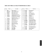
Page 29: ...Spring 20 736 0119 Lock Washer 21 736 0169 Lock Washer 22 736 0174 Wave Washer 23 736 0188 Flat Washer 24 736 0242 Belleville Washer 25 736 0463 Flat Washer 26 737 3007 Grease 27 738 0281 Shoulder Screw 28 741 0245 Hex Flange Bearing 29 741 0309 Flange Ball Bearing 30 741 0475 Bushing 31 741 0493A Flange Bushing 32 756 0178 Flat Idler 33 784 5618 Bearing Housing 34 784 5632 Auger Idler Arm 35 784 ...

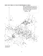
Page 30: ... 47 36 47 11 41 42 11 9 43 16 30 9 51 13 9 26 34 4 25 7 54 55 57 53 31 21 NOTE For painted parts please refer to the list of color codes below Please add the applicable color code wherever needed to the part number to order a replacement part For instance if a part numbered 700 xxxx is painted polo green the part number to order would be 700 xxxx 0689 Polo Green 0689 Powder Black 0637 SEARS CRAFTS...

Page 31: ...32 0264 Extension Spring 28 736 0105 Bell Washer 29 736 0160 Flat Washer 30 736 0169 Lock Washer 31 736 0188 Flat Washer 32 736 0351 Flat Washer 33 736 0626 Flat Washer 34 737 0170 Lubricant 6 in 35 737 3007 Grease 36 738 0924 Shoulder Screw 37 741 0597 Hex Flange Bearing 38 741 0598 Hex Flange Bearing 39 741 0600 Ball Bearing 40 741 0701 Flange Bushing 41 746 0897 Auger Clutch Cable 42 746 0898 D...

Page 32: ... 20 46 12 41 47 46 20 12 20 11 9 16 36 69 60 60 68 69 68 14 70 72 73 72 73 58 58 74 76 NOTE For painted parts please refer to the list of color codes below Please add the applicable color code wherever needed to the part number to order a replacement part For instance if a part numbered 700 xxxx is painted polo green the part number to order would be 700 xxxx 0689 Polo Green 0689 Powder Black 0637...

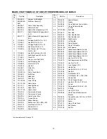
Page 33: ...6 0159 Washer 5 6 I D 39 736 0506 Special Washer 40 736 0509 Special Washer 41 737 0133 Grease 43 746 0896 Chute Deflector Control Cable 44 746 0901 Chute Deflector Cable w Clip 45 747 0798A Shift Rod 46 747 0877 Cam Rod 47 748 0362 Cam Handle Lock 48 748 0363 Pawl Handle lock 49 749 0908A Right Handle 50 749 0909 Left Handle 51 784 5594 Cable Bracket 52 784 5604 Chute Tilt Handle 53 784 5619A Shi...

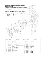
Page 34: ...ly 16 5 x 4 8 steerable 2 738 0994 Axle 0 75 dia x 12 201 Lg 3 714 0143 Klick Pin 3 Key No Part No Description 1 712 0324 Hex Lock Nut 1 4 20 2 732 0705 Cable Guide 3 Craftsman Engine model 143 999005 2 1 3 SEARS CRAFTSMAN 9 0 H P SNOW THROWER MODEL 247 888520 ...

Page 35: ... V Belt 21 754 0430A Belt 22 756 0313 Flat Idler 23 756 0569 Pulley Half 24 756 0967 Auger Pulley 25 756 0986 Pulley Half 26 756 0987 Pulley Half Ref No Part No Description 11 3 4 17 8 1 18 3 26 20 25 14 2 22 9 6 12 16 23 21 23 21 23 13 15 5 24 19 7 10 IMPORTANT For a properly working machine use Factory Approved Parts V Belts are specially designed to engage and disengage safely A substitute non ...

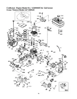
Page 36: ...36 Craftsman Engine Model No 143 999005 for Craftsman Snow Thrower Model 247 888520 ...

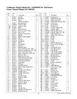
Page 37: ...915A Intake Pipe Gasket 1 1 35385 Cylinder 1 2 27652 Dowel Pin 2 3 650820 Screw 2 4 Oil Drain Extension 1 5 30969 Extension Cap 1 15 30699C Governor Rod 1 15A 30700 Governor Yoke 1 15B 650494 Screw 1 16 33454 Governor Lever 1 17 29916 Governor Lever Clamp 1 18 651028 Screw Torx 1 19 34663 Speed Control Spring 1 20 35319 Oil Seal 1 25 36460 Blower Housing Baffle 1 26 650561 Screw 2 28 30322 Lock Nu...

Page 38: ...cking Plate 1 277 651002 Screw 2 281 33013 Starter Bubble Cover 1 282 650760 Screw 1 285 35985B Starter Cup 1 287 29752 Nut Lock Washer 4 290 30705 Fuel Line 1 292 26460 Fuel Line Clamp 4 298 650665 Screw 2 300 34156A Fuel Tank 1 301 35355 Fuel Cap 1 305 35554 Oil Fill Tube 1 307 35499 O Ring 1 308 35540 Fill Tube Clip 1 310 36205 Dipstick 1 314 650873 Screw 1 315 611111 Alternator Coil 1 323B 611...

Page 39: ...tle Crack Screw Idle Speed Screw 1 18 630766 Tension Spring 1 20 640016 Idle Restrictor Screw 1 20A 640053 Idle Restrictor Screw Cap 25 631951 Float Bowl Ass y Incl 32 33 1 27 631024 Float Shaft 1 28 632019 Float 1 29 631028 Float Bowl O Ring 1 30 631021 Inlet Needle Seat Clip Incl 31 1 31 631022 Spring Clip 1 32 27136A Bowl Drain Ass y 1 33 27554 Drain Plunger Gasket 1 36 640005 Main Nozzle Tube ...

Page 40: ......

Page 41: ......

Page 42: ......

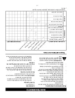
Page 43: ...vicio de reparación a domicilio Llame 24 horas al día 7 días a la semana 1 800 676 5811 Sears se complace en ofrecer a sus clientes servicio de reparación de aparatos electro domésticos y electrónicos de todas las marcas En Sears usted puede contar con operadores en español a los que puede llamar sin cargo alguno ...

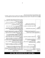
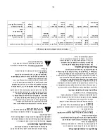
Page 44: ...l motor empacado con su unidad o haga ajustar su carburador por un distribuidor autorizado de servicio Vibración excesiva Piezas flojas o dañadas de la espiral sin fin Apague inmediatamente el motor y desconecte el cable de la bujía Ajuste todos los pernos y tuercas Efectúe todas las reparaciones necesarias Haga que la unidad sea reparada por un distribuidor autorizado de servicio si la vibración ...

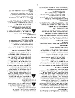
Page 45: ...e para minimizar la formación de depósitos de goma de combustible durante el almacenamiento Siga siempre la relación de mezcla indicada en el recipiente del estabilizador haga funcionar el motor por 10 minutos por lo menos después de agregar estabilizador para permitirle que llegue al carburador No drene el carburador si usa estabilizador de combustible ADVERTENCIA Drene el combustible dentro de u...

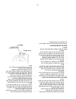
Page 46: ...e campios Friccion NOTA Coloque el piñón en el eje hexagonal si el mismo cayó de la limpiadora de nieve al extraer el eje hexagonal Coloque en posición el cubo hexagonal del piñón hacia la rueda de fricción al deslizar el piñon sobre el eje hexagonal Vea la Figura 34 Figura 34 Alinee el eje hexagonal con el rodamiento derecho y guíe cuidadosamente el rodamiento izquierdo dentro del lado izquierdo ...

Page 47: ... nieve o coloque un trozo de plástico debajo de la tapa de gasolina Incline la limpiadora de nieve hacia arriba y adelante de manera que se apoye sobre la armadura Extraiga los seis tornillos de la cubierta del bastidor debajo de la limpiadora de nieve Vea la Figura 30 Extraiga la clavija clik que asegura la rueda izquierda y extraiga la rueda del eje Extraiga los cuatro tornillos que aseguran la ...

Page 48: ... a la armadura de las espirales sin fin y coloque las dos correas en las poleas delantera y posterior del motor Vea la Figura 29 Figura 29 Nivele el conjunto del bastidor e incline hacia adelante la armadura de las espirales sin fin para alinear los pernos prisioneros con los orificios correspondientes a ambos lados del conjunto del bastidor Empuje el conjunto del bastidor completamente sobre los ...

Page 49: ...ías incluyendo pernos de carro arandelas belleville y tuercas Perno de Perno de corte corte Plancha raspadora Zapata Perno del carro deslizante del carro Perno hexagonales que fijan la plancha raspadora al bastidor de la limpiadora de nieve Vea la figura 22 para la ubicación de la plancha raspadora Reensamble la nueva plancha raspadora asegurándose que las cabezas de los pernos de carro estén del ...

Page 50: ...as las posiciones de la palanca de cambios Con el embrague de tracción enganchado la rueda de fricción debe tocar la plancha del propulsor ilustrado en la figura 21 Si fuera necesario ajustar afloje la contratuerca del cable del propulsor de tracción y enrolle el cable hacia adentro o afuera según sea necesario Vea la figura 19 Ajuste la contratuerca para asegurar el cable cuando se alcance el aju...

Page 51: ...nivel de aceite Extraiga el tapón de llenado de aceite y a varilla medidora Frote limpia la varilla medidora insértela firmemente dentro del orificio de llenado de aceite Extraiga la varilla e inspeccione Si el aceite no está hasta la marca FULL en la varilla agregue aceite 5W30 Para cambiar el aceite cada 25 horas de operación usted tendrá primero que drenar el aceite usado del motor y llenar con...

Page 52: ...TANTE Mantenga toda la grasa y aceite fuera de la rueda de fricción y de la placa propulsora Mecanismo De Cambios Lubricate Lubrique el mecanismo de cambios y los puntos de pivote en la vara de cambios con aceite de motor una vez por temporada por lo menos o después de cada 25 horas de funcionamiento Propulsor De Traccion Control Del Propulsor De Traccion Lubrique las levas en los extremos de las ...

Page 53: ...iempre que se requiera una tracción adicional Consejos De Operacion NOTA Dado que el motor no desarrollará su potencia plena hasta que alcance la temperatura de operación permita que el motor se caliente por unos pocos minutos ADVERTENCIA La temperatura del silenciador y de las áreas circundantes puede exceder 150 F Evite esas áreas Limpie la nieve inmediatamente después de caer para una limpieza ...

Page 54: ...minutos antes de apagar para ayudar a secar la humedad del motor Proceda como sigue para evitar una posible congelación del arrancador Arrancador eléctrico Conecte el cordón de potencia a la caja del interruptor del motor a continuación a un receptáculo de 120 voltios de CA Con el motor funcionando oprima el botón del arrancador y gire el arrancador por varios segundos El sonido raro emitido al gi...

Page 55: ...la hélice Para apagar el motor empuje la palanca de control del acelerador a OFF y extraiga la llave de encendido No gire la llave Llenado De Gasolina Y Aceite Preste servicio al motor con gasolina y aceite según las instrucciones del manual del motor empacado separadamente con su limpiadora de nieve Lea cuidadosamente las instrucciones ADVERTENCIA Nunca llene el tanque bajo techo con el motor fun...

Page 56: ...ro derecho cuando gire a la derecha y el gatillo izquierdo cuando gire a la izquierda OPERACION CUMPLE CON LOS REQUERIMIENTOS DE SEGURIDAD ANSI B71 3 Los expulsores de nieve Sears conforman con las normas de seguridad del American National Standards Institute ANSI ANTES DE HACER FUNCIONAR SU EXPULSOR DE NIEVE LEA ESTE MANUAL DEL PROPIETARIO Compare las ilustraciones en este figura 17 con su expuls...

Page 57: ...es afloje la tuerca de seguridad en el cable del propulsor de tracción y enrosque el cable una vuelta Vuelva a inspeccionar el ajuste y repita según sea necesario NOTA Para más detalles refiérase a la sección de Ajustes Ajuste de la Zapata Deslizante Puede cambiarse el espacio entre la placa raspadora y el suelo ajustando la zapata deslizante Retorne la palanca de transferencia de peso mostrada en...

Page 58: ...tería Vea la Figura 14 Adaptador del tambor Cable Ranura Conjunto del gatillo Armazón del gatillo El cable calza en este extremo Asegure con el tornillo Tuerca Ranura Trigger cable del gatillo trigger Gatillo de giro soldada Figura 14 Asegure el cable del gatillo de giro izquierdo de la misma manera Corte los extremos excesivos de cada amarre de cable NOTA El amarre del cable del lado derecho debe...

Page 59: ...que la palanca de cambios en la posición de sexta 6 velocidad Adaptador Contra Mango del embrague en Z seguridad tuerca de Figura 11 NOTA Puede ser necesario mover la palanca de cambios fuera de la posición de sexta velocidad y moverla hacia la posición de quinta velocidad hasta que el casquillo se deslice dentro del orificio sin fuerza Coloque el extremo doblado de la vara de cambio dentro del or...

Page 60: ...esta área por el Soporte del Panel de las Manijas Manija de la Canaleta Soporte de la manija Perno del carro inferior de la canaleta Contratuerca hexagonal Figura 7 Deslice la manija superior de la canaleta dentro de la manija inferior de la canaleta según se muestra en la figura 8 Alinee los orificios en las dos partes de la manija de la canaleta y asegure con el broche del cabello del grupo F de...

Page 61: ...ernos hexagonales al fondo del mango a continuación los pernos del carro y finalmente los pernos hexagonales en el reverso del panel del mango Fijacion De La Canaleta Coloque el conjunto de la canaleta sobre la abertura de la canaleta con la abertura en el conjunto de la canaleta enfrentando la parte delantera de la unidad NOTA Asegúrese que los cables de la canaleta estén rectos mientras ensambla...

Page 62: ...ios f Conjunto de ferretería Sugerencias de ensamblado Para facilitar el ensamblado extraiga la canaleta de la caja y colóquela sobre el motor No desenvuelva la Panel de Mango Mangos Canaleta Vara de Manivela de Parte Parte Parte Parte posterior la canaleta cambios derecha izquierda delantera Figura 1 canaleta hasta después de instalar el panel del mango los cables del embrague y la cubierta de la...

Page 63: ...dad 4 Arandela acopada 4 Retén del reborde de la canaleta 3 Broche de cabello 1 Arandela Tuerca con Tuerca hexagonal 4 Aleta del 5 16 18 x 1 75 5 16 18 x 75 1 4 20 x 75 5 16 18 x 1 50 5 16 18 1 4 20 G Tuerca soldada plana 2 Amarre del cable 2 Perno de corte 2 Arandela de 5 16 18 x 1 5 Arandela plana 2 Casquillo Broche de cabello 2 Tornillo Phillips Gatillo de 2 1 6 3 8 5 16 CONJUNTO DE FERRETERIA ...

Page 64: ...mbién disponibles en la mayoría de las tiendas minoristas de Sears y centros de catálogos y servicio Cuando usted provea el número de modelo de su expulsor de nieve la ma yoría de las tiendas de Sears pueden ordenar piezas de repuesto para usted Correa Barra raspadora Aceite de dos tiempos Bujía Recipiénte de gasolina ...

Page 65: ...una velocidad demasiado elevada Nunca opere la máquina a altas velocidades de transporte sobre superficies resbalosas Mire hacia atrás y sea precavido al retroceder Nunca dirija la descarga hacia los observadores ni permita que nadie se pare delante de la unidad Cuando transporte o no esté en uso desconecte la potencia al colector propulsor Use sólo aditamentos y accesorios aprobados por el fabric...

Page 66: ...iende específicamente por el fabricante Antes de comenzar a despejar la nieve permita que el motor y la máquina se ajusten a la temperatura exterior Durante la operación o mientras efectúa un ajuste o reparación use siempre lentes de seguridad o protectores de ojos para proteger los ojos contra objetos extraños que puedan ser despedidos por la máquina en cualquier dirección OPERACION No coloque la...

Page 67: ...usa de abuso o negligencia por parte del operador incluyendo cigüeñles doblados y la falla en mantener el equipo de acuerdo con las instrucciones contenidas en el manual del proprietario El servició de garantia esta disponible si se devuelve el expulsor de nieve Craftsman al centro departamento de servicio de Sears mas cercano en los estados unidos Esta garantiá se aplica solamente mientras este p...

Page 68: ...LSOR DE NIEVE 9 CABALLOS DE FUERZA No De Modelo 247 888520 Precaución Lea y siga todas las reglas e instrucciones de seguridad antes de operar este equipo Sears Roebuck And Co Hoffman Estates IL 60179 USA Form No 770 10057B 10 98 ...

Reviews: